The light white - an eMTB jump story

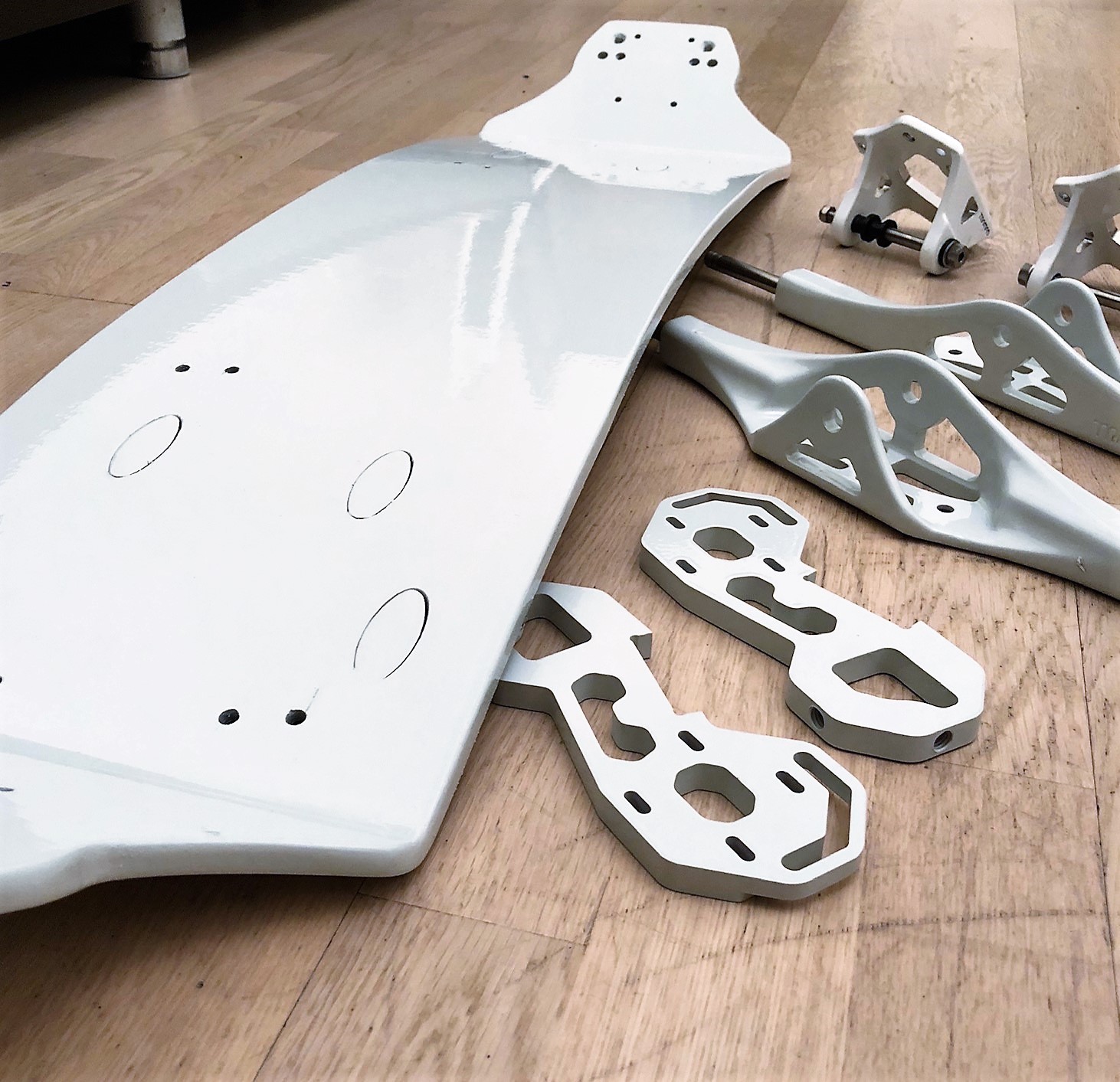
After my quad MTB build I still had one Trampa holy pro 15ply deck laying around, so I decided it´s time to build a second e-MTB.
I really like my quad, but to be fair, with it´s 25kg it´s just huge and heavy and some kind of flexibilty while riding gets lost with it.
Goal for this build was to hold the weight down at 12-13kg (including battery). That´s a pretty good weight for a solid e-MTB and a perfect base for any kind of jump activity.
The build is still in progress, so some components will be changed during this year, but here the base of parts I used:

  • Trampa holy pro 15ply (custom colored)
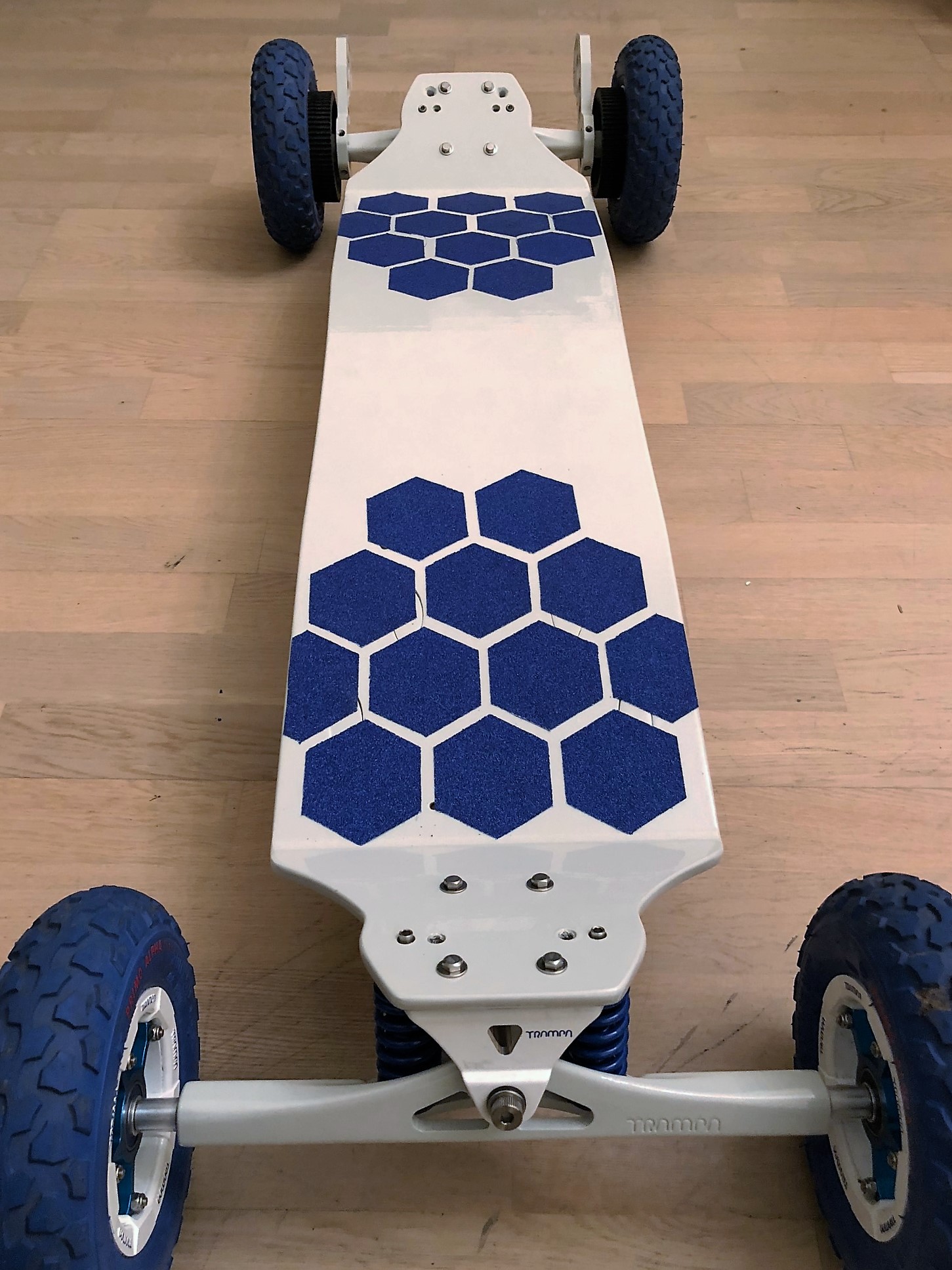
  • Trampa Ultimate trucks with Etoxx Elastomer damper
  • Trampa bindings with heel straps
  • Trampa Superstar hubs with 8" wheels
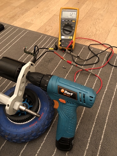
  • Motor mounts are from a forum member
  • 3D printed HTD5M wheel pulleys
  • 2x Focbox in 3D printed case and additional heat sink
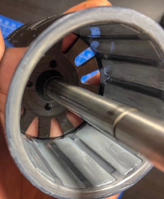
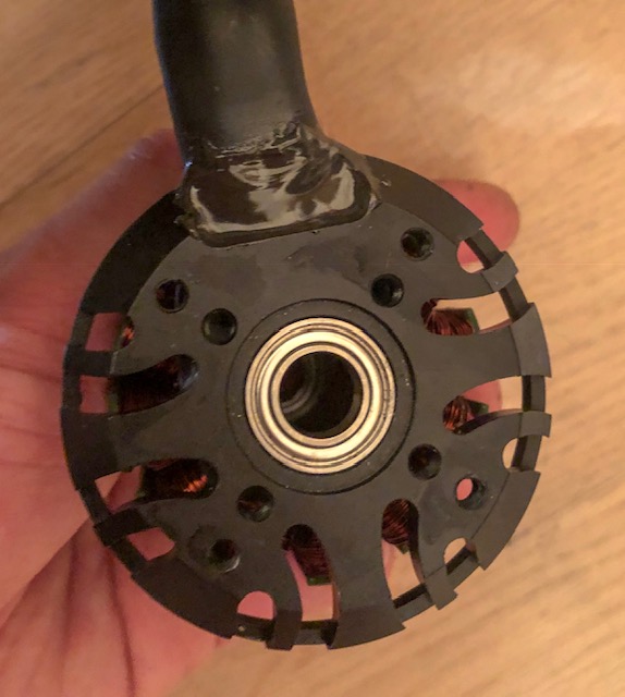
  • 2x ABS 6384 170kV
  • DaveGA speed/voltmeter
  • GT2B remote
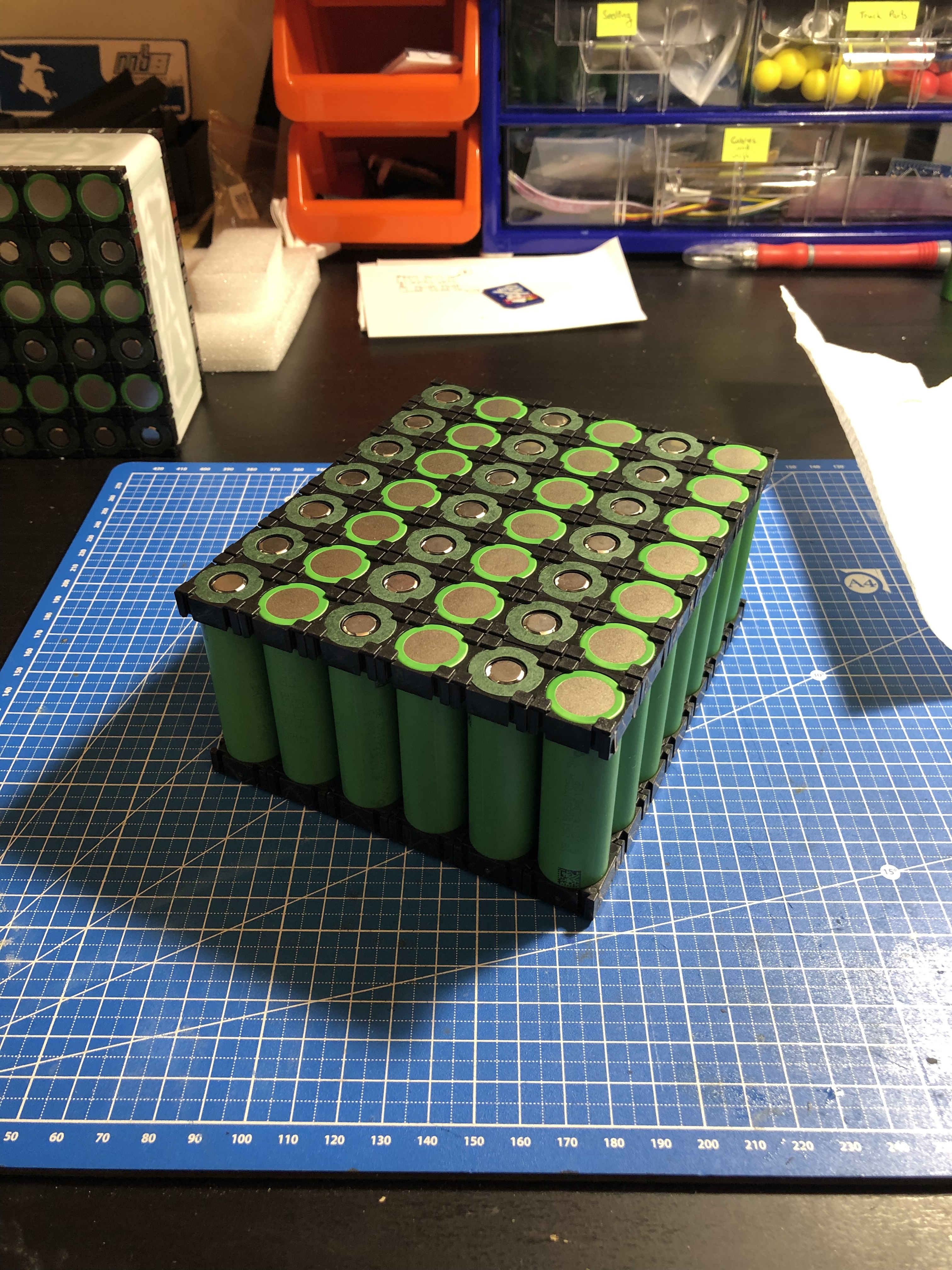
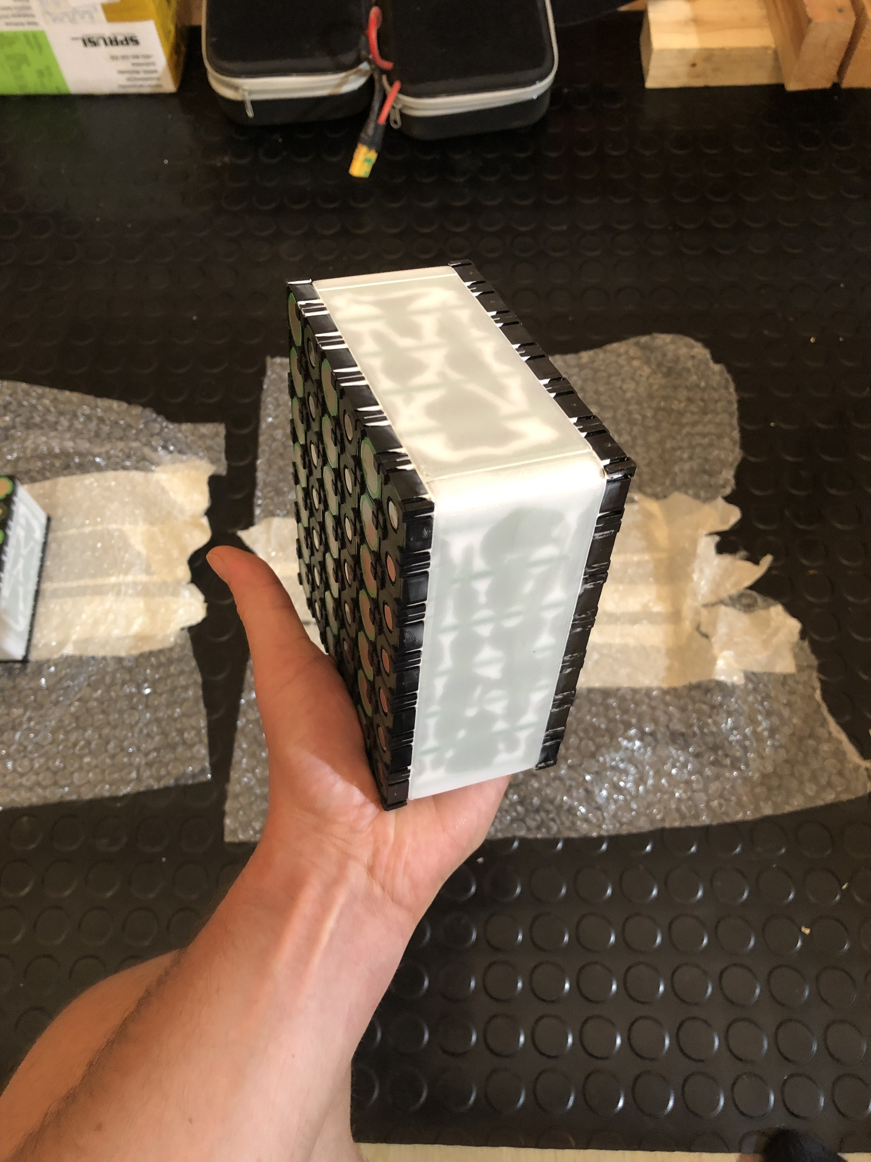
  • 2x Turnigy heavy duty 6s 5Ah 60C lipos
  • Battery case is a GoPro case for now, will be changed to a 3D printed case as well.

Ok, so “light” should be clear now, but why “white”…Trampa decks are usually dark…
Because it´s custom painted. With automotive color.
Let´s get some pictures into this thread as well.

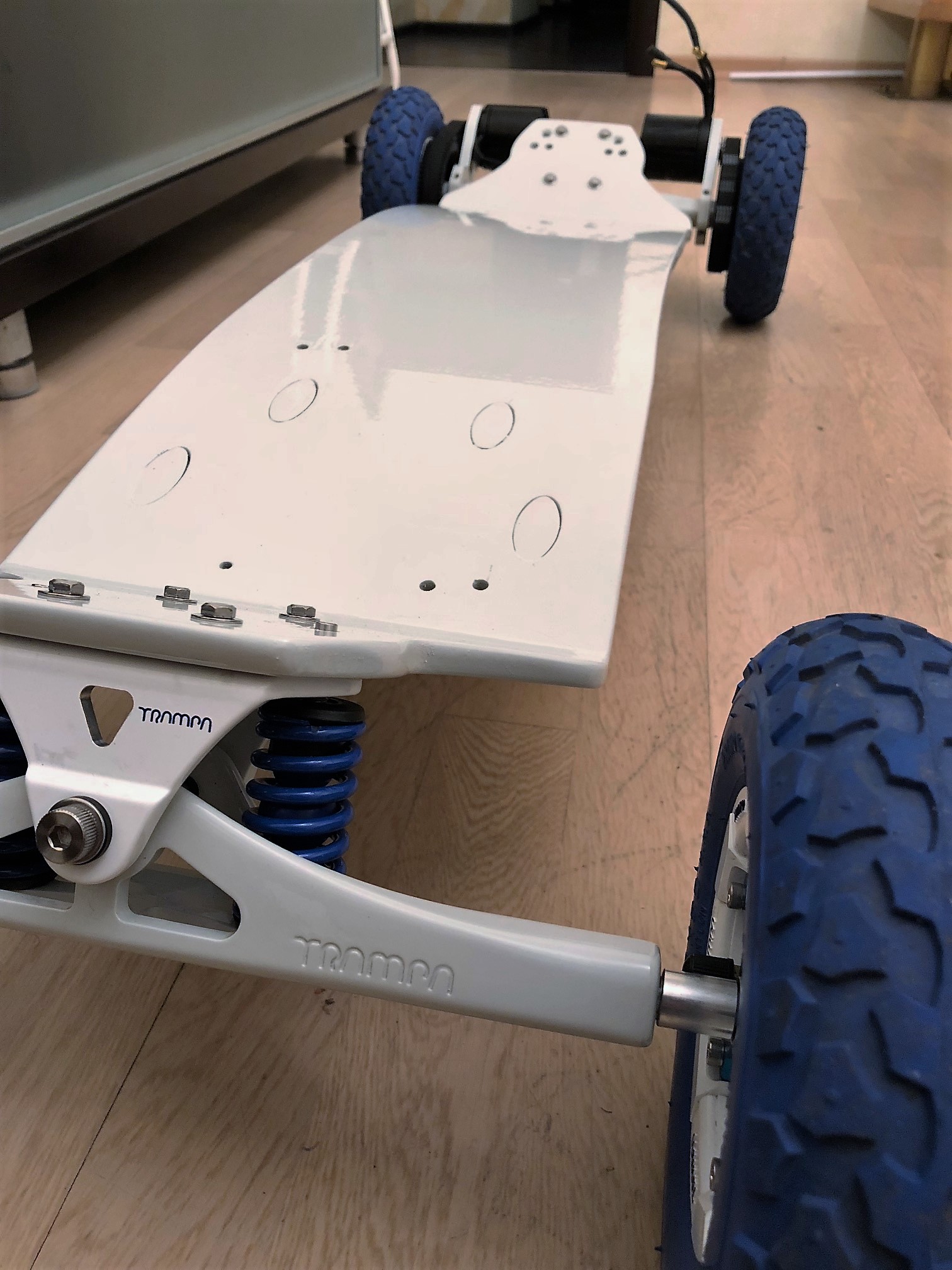
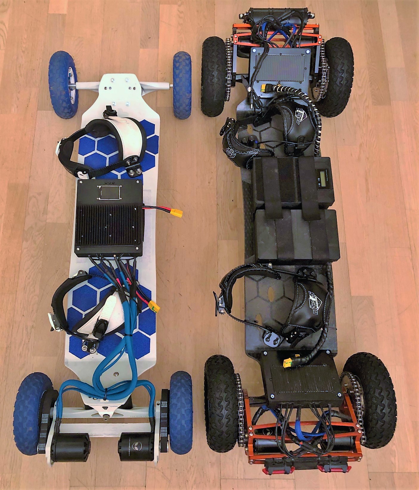
The overall weight for now is 13,6kg and with it still in the range I want to. I will change the steel crossbar (yes steel…I dindn´t have had something else to hand) against a carbon fiber one. I might also change the 6384 motors to a smaller size like 6355 or similar which should result in about 800g less weight.

The holes of the deck are covered with 3D printed covers as I first planed to use that deck with an underboard tray.
During building I realiued that it´s not going to be a street board anyway so there is no sense for this bóard to mount the battery below the deck.

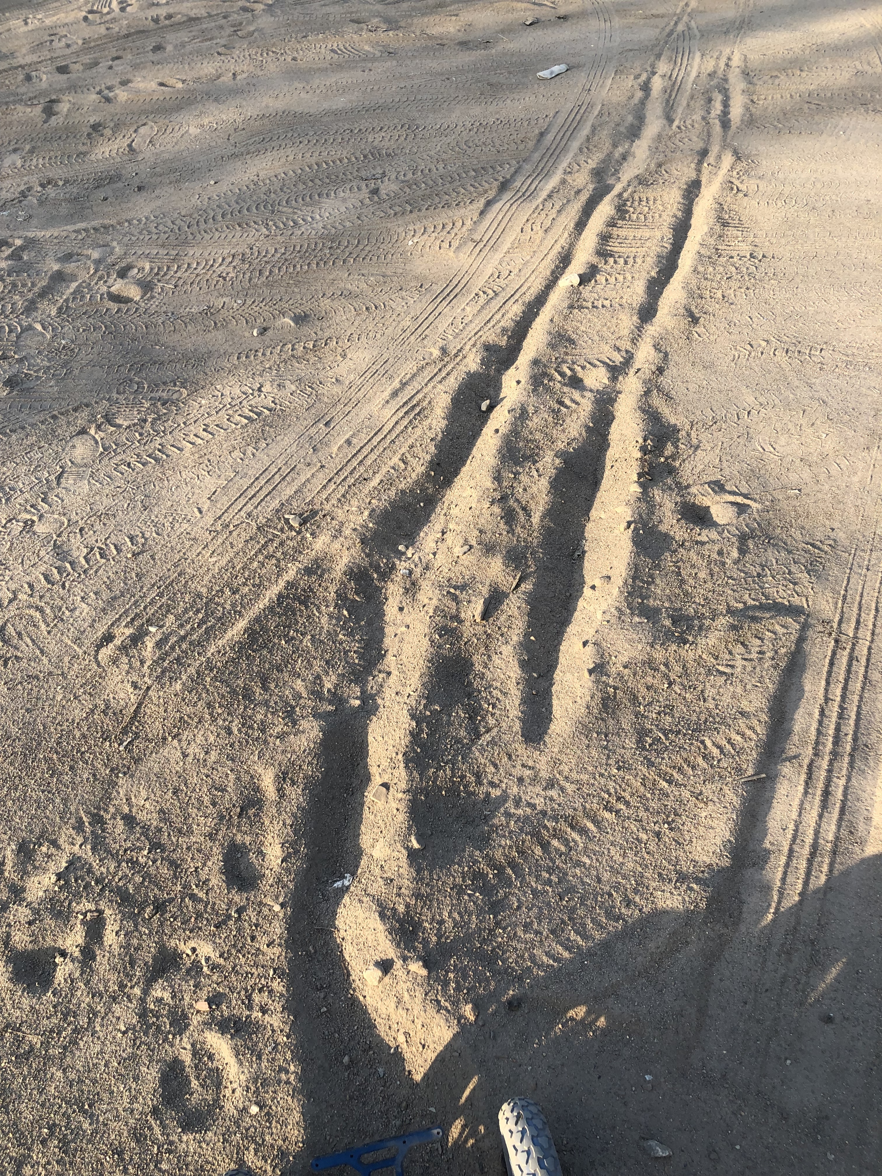
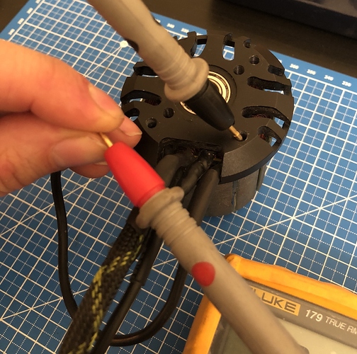
During the winter I changed the wheels to a DIY studded wheels. For those who interested in it, I will update this thread with a small “how to” comment in future.

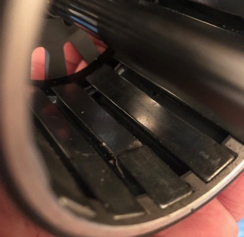
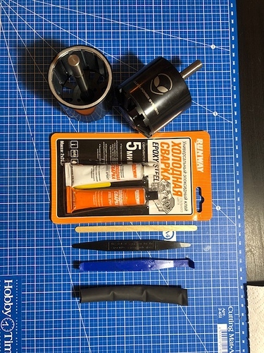
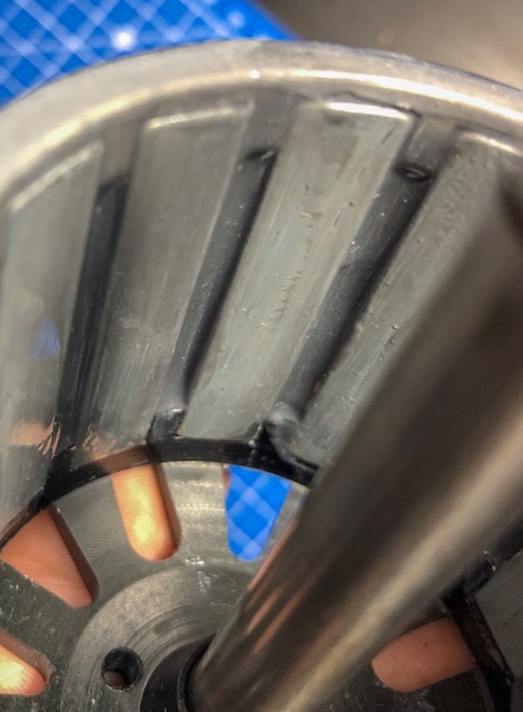
I also had massive problems with lose/broken magnets on APS motors. I fixed this issue by battle harden the bell of the motors with epoxy. I might write a small “how to” for this as well in future.

36 Likes

Looks sweet Andy. I expect 5m aerial shots this summer with a Starbucks in your other hand

10 Likes

snow finally gone and I can slowly start into the season. I will try my best :wink:

6 Likes

At first I thought these were in runners, like 35*100 size and I was like waaaaaaaaaht!

7 Likes

not so bad idea…might consider that for an update :wink:

1 Like

Let´s bring some more usefull information to this thread.

A while ago I shorted 3 of my motors because the mounting screws where 1mm too.
Due to vibrations the screws rub off the isolation and than shorted the phase wires to each other via the motor case.
Here is the way how I fixed it and double checked that everything works without issues.

I measured the resistance from the mounting hole to the phase wires like this
1

That gave me 0 ohms, so a full short.
I thought I can easy fix it by just adding a piece of heat shrink over the wires, but there is no way to get it there without to take off the top part of the stator. As this part is usually glued in it’s pretty much not possible without proper tools.
(Or as min not for me as noob :sweat_smile:)
I first tried to cover the damaged part of the wire with liquid tape, what worked out, but I wasn’t super happy with it.
I decided to make that thing bullet proof by epoxy the phase wires all over the place where they where damaged.
That looked now way much better, but the question was,
how to double check if really all damaged parts of the isolation now covered?
Sure you can just spin it up with your ESC but with it you risk to fry one more controller.
So how to do it without? :thinking:
Our outrunner produce a specific current and voltage when spinning (regenerativ breaks), so if all phase wires are ok, than the voltage produced while spinning should be the same for all three wires, right?
Right, and here is the most easy way to check that.

You need your motor on the motor mount
You need a drill
And you need a multimeter set to AC voltage
2

Connect your multimeter first to phase A and B
Than connect the drill to your motor shaft
Spinn up the motor with the drill
Check the voltage on your multimeter and remember what was displayed
Than move on and connect the multimeter to phase A and C
Spinn up the motor again
The voltage reading should be the same now
If yes move on and connect your multimeter to
Phase B and C
Same test, same result.

If in all three cases the indicated voltage is the same, you good to go and can use your motor like before.

Dissclaimer: I know there are other methodes to check if the phase wires have a short, like the hand test as well as the easy way to check just the resistance of the phase wires. What I hope do detect with this variant is a “light” short, means it´s not a permanent short. Maybe there is still a small gap between the shorted points, or the short only show up in time of rotation, or due to vibration.

10 Likes

And as promissed here a small “how to battle harden outrunner”

Yes, I had a lot of motors with lose magnets, which most time result in broken magnets as I just realized it when it was too late.

I´m very tired from this picture:
1

So I was looking for a way to make my motors more reliable and came accross the “battel hareden” thing.
But what is battle harden?
Battle harden means to fill all gaps in the motor with epoxy. A really well made motor should already come like this (some maytech motors and the new torqueboard motors for example have epoxy filled gaps in the motor bell)
This way the magnets are more strong fixed and should withstand even an impact.

What do you need?

  • Epoxy (maybe also some thickener for your epoxy)
  • some wooden sticks
  • heat shrink big enough to cover the motor shaft
  • cups for mixing
  • lots of papers
  • gloves if you want

2

How it works?
If you too lazy to read through, watch this video:

In the description you will also find some product information.
As I sourced all my stuff locally I´ll not link anything.
The epoxy I use is a 4min epoxy used for motor and car stuff.
For me it has the perfect consistence. It´s fluent but still thick enough to don´t run away from the holes.

First you need to take appart the bell from the stator.
Than you want to remove the shaft.
As this might be not comfortable for most of us, you can just cover the shaft with heat schrink in the right size.
You really don´t want to get some epoxy on the motor shaft.
If you work on an old motor it makes sense to clean first the bell and make sure everything is dry before you continue to apply the epoxy.
Depending on how fast your epoxy is getting dry and how fluent it is, you will need to mix up more or less epoxy.
For me it worked best doing 3 lines than clean up everything, wait 3-4 min and continue with the next 3 lines.
If you mixed up the epoxy you fill the space between the magnets with it. Probably your magnets will be covered with some epoxy too. Use the wooden sticks to clean the magnets as good as possible.
Repeat this till all your magnets glued in and it looks like this or better :wink:

It´s recommended to let the bells sit like this as min one day.
During this time I had a look at the stator too.
Here you could do the same with all windings.
It could probably help if you have a slightly lose winding or strange high pitch noice coming out of the motor at a specific speed.
I for my own deceided that it´s not really necessary.
One thing I didn’t like on the motors, that the phase wires are pressed to the housing. In this place the windings also soldered to the flex awg cable. I have seen pictures of broken/cut isolation exactly in this place, that´s why I decided to cover this place with epoxy too and restrict the cable moving to like zero.

If you plan to do this as well, take care that the phase wires are in the right angle coming out of the motor. If they stay up too much it´s not possible to mount your motor later :sweat_smile:
One more thing you could do in the same time, cover the sensors and pcb with some lack or epoxy too.
waterproofing your hall sensors can save you from a lot of troubles.

Ok, so it´s time to put everything together again.
Turn the bell with your hand and make sure nothing is rubbing.
if it is, some 500 sandpaper can help to get rid of this.

I also recommend to do a new motor detection after you assembled everything back, to make sure everything works how it should.

Happy riding!

19 Likes

I admire your persistence and resolve but you really need to reconsider your motor choice.:grin:

6 Likes

:thinking: the point is, nowadays you never know. Even if you buy from a good company you can get a bad batch or they just changed the producer or you just unlucky to get a bad motor. So in a way i know where the weak points in the motors I bought and I know now how to make them more reliable or fix the issues. Theoretically i can just continue buying the same, just need to spend some time to modify them from the beginning :joy:

8 Likes

Probably not :joy: but non the less very interested how you did the harden thing your way.

1 Like

Short update from the light white out in the wild.

16 Likes

I want to ride a board like this one day :joy:

1 Like

I want to ride this board with your gears :joy:

My chains didn’t like that sand hole so much last time…

Locked up at 25km/h. Was a nice spill. Still have sand in my teeth :joy: jk…really good that I always in full gear when i‘m out for a mtb session.

9 Likes

@anon54720240 he go hard :joy:

Hands still too shaky for the hardening of battles thanks for tips gents

Pfffff that looks like talcum powder so there is usually a stone in there to give an owwie?

It was pretty hard sand/dirt, but than suddenly :sweat_smile: it was like on the beach…just the fresh salty wind was missing. Instead I inhaled some good old fine sand.

4 Likes

Last year I bought a punch of vtc5a cells but they never went into the build they where planed for. As summer is in full Progress it’s nice to have a pack which gives you a bit more range. As lipos get very heavy compared to 18650s if you want to get some range out of your pack I decided to use this cell for the light white.
My goals where:

  • decent range about 30km
  • 3.5-4.5kg max weight
  • decent discharge
  • easy interchangeable
  • shouldn’t influence the flex of the deck
  • charging and balancing with 6s hobby charger or optional 12s fast charger possible

That’s why I decided to go with a 12s7p split into two 6s7p packs.
I decided that size doesn’t matter so much in this config and went with plastic spacer/holder to hold the cells in place.
In addition I 3D printed some petg covers for the side and glued them up with neutral silicone.

I cut the H-formed nickel first and soldered the bus bars as well as the balance wires onto the nickel before I started to weld them on.

To weld the nickel to the cells I used a malectrics spot welder with a 3s 5Ah hobbyking graphen pack.
Always test your welds on some old cells before you start welding your pack to find the right pulse time. My welds where pretty solid at 8-10ms. With a higher pulse time the welds started to get dark which is not ideal.
If you use other lipos this might be different. Other people had good and solid welds only with 18-20ms.

One very simple but important tip I got from @taz , always cover the parts on your battery you actually don’t work on with masking tape.
You don’t want accidentally short something by placing the nickel strip on the wrong cells or what ever can happen during building process.

The packs where covered in clear heat sink.
Makes things easy to inspect from time to time.
Each pack has as well a 58V 100A fuse on the positive wire, plus xt90s as connection plug.

For easy access the balance wires are routed out of the box and covered with some neoprene velcron tape.

I could velcron the packs to the deck, but it’s a pain to get them off if they stick strong to the velcron, so I decided to go with a combination of two screws and two slim strips of velcron to fix the packs to the deck.

Next thing I have to do now is to drill the holes in the deck and place the threaded inserts as well as move my esc box on the back of the deck (till now it was placed on top of the battery pack)

Mounted updates will follow.

13 Likes

Keep it there. More weight on the ends of the board make for worse handling.

1 Like

Some footage from one of my last rides

image

And a looong clip from one lap around my nearby field

Aaaand one after work session

Still a lot to practice for me.

21 Likes

Thats definitely right, but as the balance wires and main leads come out to the top of the pack it’s not possible to mount the vescs on top anymore.

2 Likes