The Avio Mini Remote Mod
Parts List:
- Two (2) 3D Printed casings (Top and Bottom Cover). Download the files here: The .stl files will be constantly updated and improved, so don’t be alarmed if the pictures you see in the instructions differ by a little
The Avio Mini Remote Mod! Short and a Long version! More information can be found here: https://www.electric-skateboard.builders/t/the-avio-mini-remote-mod/72074 There are 2 different cover types, one that allows for the installation of a Battery…
Things that are reused from the Mini Remote:
- Two (2) “Big” screws and Five (5) small screws with one (1) M2 or M3 nylon washer
- One (1) Spring Lever
- One (1) Spring
- One (1) Throttle Arm
- One (1) Potentiometer Assembly
- One (1) Mini Remote PCB
Things you will have to purchase:
- One (1) 5v to 3.3v Regulator
- One (1) TP4056A (Micro USB) PCB
- One (1) LP103035 or smaller battery
- One (1) Battery Indicator
- One (1) Wrist Strap (Optional)
- 30AWG to 24AWG wires. (Min of 2 different colours)
Instructions:
First, remove your screws from the mini remote and open it up
KEEP THE SCREWS

You’re gonna need this

Cut these two wires that connect to the AA batteries.

There we go, now let’s remove more stuff.

Take this lever off, so it won’t fly out and go under your bed which you will never find forever

Remove the two screws here that attach the trigger to the casing


Then, cut or desolder these three wires that connect to the steering knob of the mini remote, we do not need that.

Okay! That’s all that we need from the mini remote. Now you can toss the casing in the trash 

Okay now onto the regulator. You need to desolder and pull out all three pins. I did it by having the solder on the other side of the pin, once the solder iron melts, i tilt and twist slightly till the pin comes loose and eventually comes out. This one’s tricky so take your time with it.


Once that’s done, you can solder the wires from the mini remote PCB in this fashion to the regulator. Red goes to OUT, and black goes to GND. Do note that the wire needs to be long enough for the regulator to extend past the PCB, so do resolder a longer wire if needed

Now, flip the regulator over to the other side. Have a new black and red wire that’s about 40mm long, cut shorter if needed later. Solder the black one on GND as well, but this time it’s below.

The red wire goes on VIN, but on the underside as well.

You should end up with this

The red wire will go to OUT+ of the micro USB PCB, and the black goes to OUT-

And finally, the battery. I had mine with the wire on the bottom left

The red wire of the battery goes on B+, and black goes to B-

And finally, use a plier to crush this LED bulb as it’ll stay on and drain your battery.

SNIP SNIP

And we have power!

Now we are done with the electronics, next thing is to install it into the remote casing.

Conformal coated all my PCBs.

I also hot glued most of the solder joints to give it a bit of strength.
Now you can double side tape the battery to the bottom of the case, and also use foam tape or double side tape to paste the PCB on top of the battery.

It might sit lower so use a foam tape that’s 1mm thick to lift it up, and align it well with the hole.

Next, hot glue the mini remote PCB and push it all the way to the edge of the casing and make sure the switch goes into the hole of the new casing as well. Remember to hot glue the regulator PCB down to prevent it from rattling as well.

Next, you need to snip of a bit of these two knobs. NOT ALL, just about half or so. This is to prevent the other side of the casing hitting it and making it impossible to close the casing due to the height.


Once that’s done, use the existing screws from the mini remote previously and screw them onto the new casing. You didn’t throw the screws away did you?

Install the lever back as well with the spring.

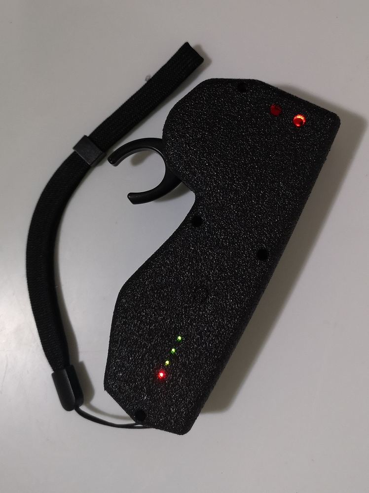
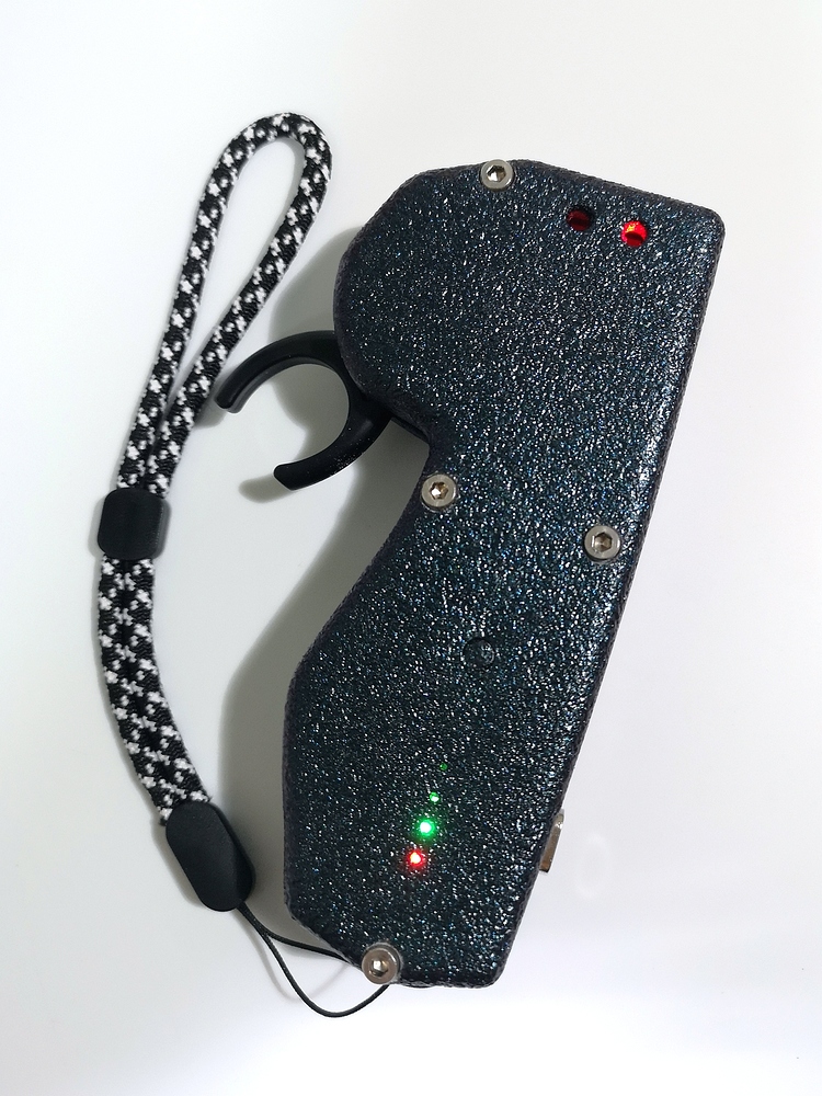
And should everything be done properly, it should look like this! The short version basically has lesser length but there’s still plenty of room. So the long one has A LOT of room haha.
Wire management is pretty good if done well. But hey it’s gonna be inside, never gonna be seen but that’s how i do things.

Place the top casing on, and use the existing mini remote screws, and plop four of them into the screw holes.

Success! Now what’s left to do is to do the VESC set up and all that jazz. It’s ready to use! For binding, you will need to use a small screw driver to press the button inside.

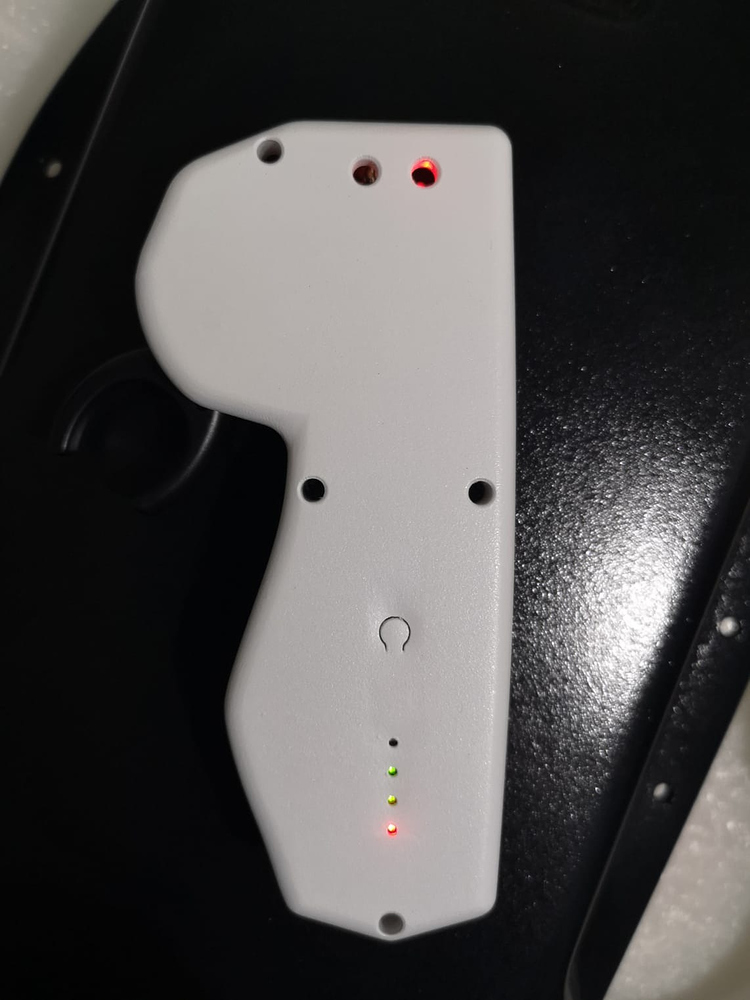
To add the battery indicator, slot the battery indicator into the insert as shown below. Secure it into the slot with 2 screws (highlighted in blue). Any black screws used in the Mini Remote will do.
Use a small nylon washer/nut between the screw and the 3d print. If not, ignore using the screws and simply use hot glue to secure it to the print, by hotgluing the edges down. It works flawlessly too.

Solder 2 wires to the positive and negative terminals of the battery indicator and connect them in parallel to your battery, (+ve connects to +ve, -ve connects to -ve).
You can simply solder them onto the inputs of the TP4056A pcb where your battery connects to! Press the button on the cover to read the battery level of the remote!
And that’s the end of it. You should have a remote that works. Please follow the steps from start to finish in order.
Optional stuff for extra awesomeness:
- Magnetic Charging!
Simply purchase a magnetic adapter and cable for $3.50usd!


- Wireless Charging!
Taking it up a notch, you can make make your remote wireless compatible by purchasing a wireless charging receiver!
Hook it up to your avio remote on the bottom of the base below where the battery sits and voila, you have wireless charging!
If you would rather have me make it for you, here’s how!
I’ve gotten rather efficient in this. So, for everyone else who wants to get their hands on this remote, I am openly now selling them on a build-to-order basis. I will order the SLA covers and required components in batches based on the orders i get from time to time. The lead time for these remotes will hence vary from 1 week to 3 weeks, depending on shipping times.
The price of the remotes are:
-
$62.5usd for the Long Remote.
I do not make short remotes anymore. Doesn’t seem to be a demand for them.
The price stated covers PayPal fees and free intl.shipping
Remotes will be printed in SLA, not FDM which makes for a much better surface finish and also painted in exclusively black truck bedliner. I realise that making remotes in 10193 different colours is a huge pain in the ass. I can still do different colours upon request, just lmk.
- Khameleon colours (+$10 usd)
(This basically makes the remote all shiny with a beautiful texture. See the first pic of this post for reference)