Originally it was to get to and from work about a 7 mile round trip mostly flat ground. But now it is to get out of the house and socialise as it will be more of a reason to move than just the need to get back into ugh cardio. Weight training will only get me so far you know?
Thank you so very much. I wasn’t making much progress on my own ![]()
It’s possible I’m just being too gentle but I’m pretty confident it’s soldered in.
You’re correct, it’s 19mm
Options were a bit slim in the automotive size but it seems like this should work right?
https://www.digikey.com/en/products/detail/optifuse/ANR80-UL-40A/11581778
Once again, thank you so very much.
That definitely looks like it should work, right size and current rating
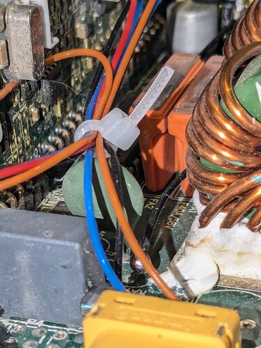
If you can get a picture from an angle of where the fuse meets the board it might be easier to tell if it’s socketed. Some barbarians do solder blade fuses directly to the board, but it’s not exactly ideal. The fuses aren’t usually very straight and upright. If you’re OK with soldering it’s not the worst job in the world, but it’s not great for the fuses to push that much heat into them
Also, have you been able to check if there’s any other damage to the charger? There are a small number of other components that could reasonably be killed by plugging in the wrong polarity. If you see anything marked TVS or “D [number]” near where the output connector is, those are top suspects. Reverse polarity could kill basically anything on the board, but the TVS or reverse polarity diodes are more likely
This was the best that I could do without removing the PCB (which I think I will have to do anyways to replace the fuse)
Nothing else seems visibly popped or burnt like the fuse does.
Nothing I can see currently, I’m going to spend some more time trying to get it the rest of the way apart, I wanna take that slow to make sure I don’t break it more while trying to fix it. Once I get the PCB out from the case (hopefully it isn’t epoxied or adhered or anything) I should be able to get a better look at how the fuse is attached and if anything else is burnt.
Your help is endlessly appreciated.
Interesting, looks like they designed in slots in the board for it. That’d explain why it looks reasonably secure there
Sounds good, slow is safe and safe is faster than fixing shit you broke
I’ve gotten it a bit more disassembled and got access to the bottom of the PCB.
1: you’re correct and those fuses are 100% soldered in. Also I’m not entirely sure if the bridge into that bar on top (circled in blue) is intentional, should I try to mate the fuse to both contacts when I replace it or just the contact on the bottom? (Circled in red)
Unobstructed view:
- Nothing looks burnt like the primary suspect but a bunch of stuff does kinda look like it’s in rough shape to me.
Is this bad enough to be concerned about?
I honestly can’t tell if those are brown burn marks or if they’re some kind of protective coating.
I’ll have a think and get back to you over the next day or two, cheers for the pics
Looking to do a chain drive build, where do people usually source their wheel sprockets?
I’m a bit less confident here so bear that in mind
I believe this highlighted reddish area is all connected. I think the white outline here is the border
The two different shades of green visible on the PCB are conductive and non-conductive areas, one has copper under it the other doesn’t. It’s not 100% clear to me which is which though. It could be that this is a big conductive plane separated by small gaps (I believe it’s this), or a big empty area and the borders are actually copper traces. Easiest way to check is to get a multimeter set to continuity mode, put one probe on one of the rails of solder and progressively tap the other probe on all the other ones. If they all beep, they’re all connected together, and that solder bridge is fine
To me that discolouration looks like it’s from the factory, at a guess either they used too much heat on that area or it’s solder flux they didn’t bother to clean off. Not very certain though, I might try and tag someone else in
I suspect there’s some kind of protective coating on the bottom of the PCB as I’m not getting continuity between 2 sides of the same solder joint. I’m going to ask the seller if that bridge is intentional before I try to remove that coating.
I thought so too.
@Pecos you recently did some work on your ningning charger to get the screen working properly right?
Did you get a look at the PCB on the bottom?
Did it look like this?
my dude says get some flux remover and a q-tip and take your time. i usually give him all my stuff just his 2cents. good luck ![]()
Thanks for the tip! I do want to make sure that the MG chemicals 419D is an acceptable substitute once I do remove it. I think it should be fine but again.
I have acquired this vesc for e bike use, could anyone tell me how should I treat the antispark situation? Vesc has auto shut off, and turns on with non latching button. Can I hook my battery for the first time without an antispark and just leave it?
In the product page it said “precharge resistor” included, I have not received such a thing, is it for the antispark? Should I just buy one?
Use an XT90S or other anti spark connector on your battery (eg. XT120, QS80, XT150)
G300! Great choice, I love mine.
Are you sure(?) it should be a cylinder thing with two metal leads in a bag with the connectors.
Short answer: kinda yes? But no. Once the battery is connected, it’s fine. The issue is plugging it in- you want to have the pre-charge resistor for this.
Long answer: Without a precharge resistor, when you plug in the battery there’s going to be a big spark. The high-temperature plasma from the arc damages your connector terminals(and can be quite loud). You could maybe accept this damage? I wouldn’t recommend it.
The reason you need the antispark is the G300 (like most vescs) have big capacitors across the power input to smooth the power flowing from the battery into the controller. A side effect of this is when you first apply power, a ton of current rushes into the capacitors, causing the spark.
Having a resistor in series with the battery significantly slows the rate they charge, preventing the arc.
Once the battery is plugged in, you no longer want to have this resistor in series because it’ll restrict power flowing into the G300 (and also likely overheat).
The reasons illustrated above is why this solution is so convenient. Take a look at this AS150 connector (what I have on Ankle Wreacher)

It is a two tiered contact. When plugging it in, initially only the tip makes contact initially. The tip is connected in series with a resistor inside that prevents a spark. Then, as you continue to push the pin all of the way in, the socket will also contact with the side of the male connector, allowing it to bypass this resistor.
If you don’t want to use an anti-spark connector, and/or you can find that pre-charge resistor that they shipped you, this is an option;
- Plug in the negative of the battery to the g300
- Holding the pre-charge resistor with a pair of pliers (because it could get hot, bridge the battery + to the G300 +.
- Hold for 5~10 seconds to make sure the capacitors are fully charged.
- Quickly drop the resistor and connect the battery+ to the G300+. The faster you do this the lower the chance there will be a spark (the capacitors slowly discharge when no voltage is applied) (Metal-to-metal contact is fine, you can take your time with the bolt/screw)
A bit Janky, but I do this whenever I need to unplug/replug Ankle Wreacher and haven’t had an issue since. (Even though I have AS150 connectors, I destroy the resistor inside a AS150 because rated for the current surge that 4x G300s pull when plugged in simultaneously at 16s)
I posted about it in my thread, you can see an example of the contact damage that can happen when there’s no anti-spark:
Also, don’t forget to use the rubber insulating rings below your terminals ![]() The housing of the G300 is connected to ground, so you don’t want stuff shorting to it.
The housing of the G300 is connected to ground, so you don’t want stuff shorting to it.
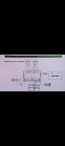
In the process of making my can cable for a 4wd setup. Do I need to do all 4 pins or just the 2 signal lines and leave out the power and ground like this diagram shows
Yeah no power wires needed. Only can-powered devices like davega and stuff need them.
![]() thanks
thanks
Yeah I was over exaggerating but I do tend to get a bit wild with it sometimes. So here I have finished most of what I can but as much as I love electronics I realize how much I just don’t know and so I’m coming here for some help. I am going to post the pics and would hope someone can possibly markup what I need to do with the wiring to have it functioning. I am still printing a larger holder for the esc and bms it’s about to be finished but they will both go in that if it makes sense to you guys. I know the bms I got is over kill even so it’s a 100 amp so I think it will probably need to be bypassed and I’m not sure how to do that. Ok pics I am still running into clearance issues with the bms and esc


