If I do this I get an overcurrent error. Am I doing something wrong?
1 Like
You could try and increase your wire length to add some resistance
1 Like
Yep you can’t do this without discharging them to rougly 12.2v or so. At 100% charge and a standard wire length setup, it’ll overcurrent.
Once they’re working though, they dont heat up at all, so the only bottleneck is the probes heating rather than the lipos (They also are healthier discharging half current)
1 Like
Has anyone else switched to using .15 nickel btw? The stuff I have tried in .2 is always very difficult to work with (doesn’t fold nicely, only can do a few welds before kweld overheats etc)
Even with p42a, when designed correctly there will be effectively no heating of the cells when at max continuous current, not to mention .15 is cheaper…
Is there a good reason to move back to .2?
1 Like
Depends on pack construction, there’s ways we could get away with 0.1 on large packs but it’s not always as simple
I exclusively use 0.15. The only times i’ve used 0.2 is when i’ve built duck pcb kits.
3 Likes
I used 0.15 before as well, but all the precut stuff these days are in 0.2
For most things, yes.
1 Like
Tbf the maximum discharge from a P42A to build in is 30A, and you’ve got 21mm width to do it. So .10 wouldnt technically cut it, although yea for like a 10P pack where 300A cont is not actually ever happening you could
If you have staggered cells there’s enough material to tile forever I think
1 Like
Hi, I ordered a Sequre SQ-SW1. I’d like to avoid spot welding using lipo or lead acid battery.
Is someone using supercapacitors like the ‘kCap ultracapacitor module’ instead of batteries with the SQ-SW1?
1 Like
Are there any comprehensive written guides for battery building start to finish? Ive picked up lots of info reading around the forum and watching videos (using hot glue to secure cells in place, magnets for spot welding, testing for pure nickel, minimising heat during soldering, fish paper, Kapton tape, bypassing bms, etc) but it would be nice to have a single source to work from
Not as yet. I’m going to be putting some work into the battery wiki along with @DeadLightning in the coming weeks. Hoping to have something much more comprehensive within a month or so.
@DeadLightning- Quinn, I’ll be in touch this wknd with an update on progress.
4 Likes
Check out @ShutterShock on youtube (RB E-Motion), he has some comprehensive guides on how to build several types of batteries.
3 Likes
If you end up having any questions be sure to post screenshots here as well
It’s RB E-Motion (youtube.com/c/rbemotion)
3 Likes
Lee wright has some solid videos as well taking you through a build. Think it’s a two episodes of him showing a mtb build from start to finish.

There’s part one.
2 Likes
Just want to bump this great alternative to the Xiaoxiang app! Super super good stuff
2 Likes
I have a couple of questions.
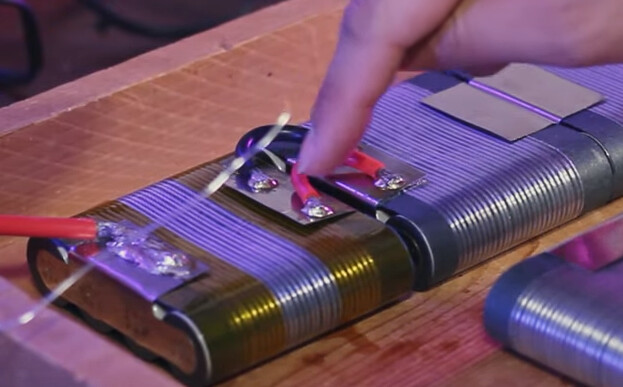
By my understanding, most flat battery packs are built like the image below. I can see how this is better for space efficiency and flexibility. Out of interest, does there need to be insulation between the P-groups (below where finger is) or is it fine as is? I’d imagine there is a risk of sparking if the two groups accidentally contact each other.
Anyway, my battery is going to look a little different:
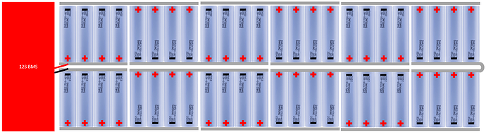
This is for a couple of reasons. Firstly, my soldering iron is a bit shite, and I don’t want to risk loading excessive amounts of heat into the cells, hence why I’ve minimised the amount of soldering required. Secondly, my deck is rigid, so I don’t need flex in the battery.
I am a little bit concerned about the space this will take up.

I haven’t yet decided on an ESC, and I will be building a custom enclosure. Do you think an area of approximately 17cm x 13cm would be sufficient for the rest of the electronics? (BMS, VESC, cables & connectors, etc) The enclosure height will be 4-5cm maximum (I may shape it such that it is tighter around the battery, and has more space around the other electronics) . These are all estimated figures.


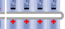
Secondly, would bending the nickel here be a concern? Could someone provide an estimate for the minimum bend radius of 0.12mm thick nickel? Or would I be better off soldering a wire between the two strips?
I’d also like to mention that I will be insulating over the top of the nickel strips in each P group to prevent the groups coming into contact on opposing sides. Would a single layer of Kapton tape be sufficient for this?
Finally, I’m a bit confused about wiring the BMS balance leads to the positive terminal of each P group. As the groups are all connected in series, how can the BMS distinguish between the groups?
I have ordered the fish paper, kapton tape, nickel and spot welder but most of the items won’t come until later in the month so I have plenty of time to ponder over this before committing to the build.
Thanks in advance.
No, as the wires bring both sides to the same potential.
Gonna be close, but depends on your BMS and ESC.
Bending is not a problem, however the cross section for that nickel is very small, hence it will heat up with current draw. Its not uncommon that it starts to glow red in those locations. Avoid such a setup at all cost. This is also the reason why the wires-on-top setup became popular, with the added benefit of being able to flex.
The voltage will rise with each group by a specific amount, enabling the BMS to distinguish and balance all groups.
Boards tend to vibrate quite a lot, so one layer of fish paper would be a minimum, a hard plastic spacer would be preferred.
3 Likes
