Place your random great ideas here (no stealing)

pulling the stator youre making a worse motor in that the airgap thickness is essentially increasing. you could similarly add crappy weak magnets and would be the same as pulling the stator.

pulling the stator does show there’s a lot more potential in the motor as far as heat produced to POWER output only in that it is increasing speed. a lot more potential is possible in all our motors and we all are barely spinning them and theyre all heavy with copper losses where if we want to get the most power output we’d ideally be balancing copper and iron losses, but doing it in a way where youre decreasing the torque to amp relationship at the same time is counter productive.

if all of us could spin our motors at like 20:1 gearing, with our .2 or .15 millimeters of laminations of great electrical steel, we could get more power to heat produced but no one is able to fit the gear.

if anyone spins their motor at its top speed with no load on the bench …that is all the iron losses the motor will produce even under a load. the difference loaded or unloaded i read is negligible as far as iron losses produced. so if you get maybe 2 amps at top speed doing that…and when youre riding youre often hitting maybe 30 amps …its very largely copper lossses and if you swapped the gearing for 20:1 maybe youd get 6 amps at top speed no load but the burden to produce torque by the motor is greatly reduced so that current draw goes way down
3 Likes

If someone doubles the kv by pulling the stator, and then also doubles the gear ratio, the copper losses, wheel torque per amp and top speed remain unchanged…

I have an idea for a board designed from the ground up for air travel.

Two carbon fiber plates, aluminum profile rails, steel angled brackets and some cheap Chinese channel trucks+ mounts I have. Battery would be some 99wh 6s lipos. Xenith Vesc and some 6374’s I have laying around.

This would all be broken down into a compact size hard case. Goal would be to make it quick to build up and break down.

I’ve never been to California and really want to, but I think it would be incomplete without a board built by me to show all you guys.

Thoughts?

1 Like

You mean a Lonestar?

9 Likes

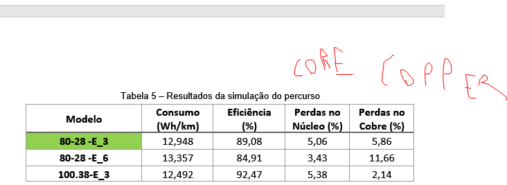
On the hubs maybe, but I did process 400 km of logs I had on my belt drive MTB. Considering the whole ride, the split between core and copper losses were almost perfectly split 50/50

This is due, at least for my riding style, the average torque being really low, so even if on hard hills and accelerating the copper losses are big, they balance out with a lower but almost constant core losses (riding as speed)

And you can do a hub that using real ride data, get a almost perfect 50/50 split on the loses, as seen on the first DD design of this table

2 Likes

why is the DD on your table getting half iron and half copper?

2 Likes

If you keep a carbon fibre box, they cannot look through it, resulting in them 100% opening it up themselves, i think Glass fibre would be better for this application.

Unless you also take that apart ofc.

1 Like

In short words, because it’s the optimal design for they way I ride, lots of candidates were considered before reaching this one

2 Likes

This is the plan. I don’t even want them to know what it is. Should look like a pile of parts. Nothing to inspect, no reason to fuck with it.

2 Likes

what motor is it or did you make it? curious what motor design is most efficient DD motors for how we use them. in my simulations, which weren’t much, getting the biggest strongest magnets in was best i could do. getting a new stator design wasn’t an option. very surprised with the motors ive been making having much lower cogging torque and went against the simulation results and common assumption as this stator has slots that are larger than the past as well.

It’s a 80 mm stator, 24S28P, I will refine it before making one day

It’s always a balance, stronger magnet is not always better, sure, you increase the motor Km, but the core loses also go up, if you are near the end of the linear saturation of the stator iron, the core loses can skyrocket

Cogging torque doesn’t mater that much since its a conservative force, of course you don’t want to be really high, but once the motor is spinning the inertia makes it not noticeable. I’ve seen some motors that you can barely spin by hand due to a high cogging torque, but once it’s spinning, it gets smooth

image

1 Like

i see no shaft on your motor

@Pedrodemio will you get a couple stators cut the electrical discharge something way?

are you still using design software?

im obsessed with cogging torque. please tell me what you think or know related to my assumptions. ive done no testing really.

in my simulation, when modeling a stator similar to the mellow hub, i decreased the slot to like .001mm i think it was and it seemed to work fine in the simulation. wouldnt the magnetic field lines jump from tooth to tooth and be lost from interacting with the magnets?

but more so still interested in cogging torque and what results youve seen, ive done no testing but just based on riding a vehicle with a magnet motor…it is a loss. a loss of momentum when coasting. i guess wouldnt be a loss when powered with foc or maybe other waveforms. have you ever seen it graphed? do you have a dyno? id like to see if it produces like hysteresis or eddies.

Ive seen some paper where more skewed teeth and reducing cogging causes more iron losses. they dont seem to go hand in hand but ive barely found anything to read.

when you say youve seen motors with high cogging in hand but spin smooth when in use going faster I believe the torque ripple is there at same strength overlaid at all speeds and the momentum of the rotor smoothens it but the loss in momentum is still there.

or what about the mellow motor with its thin slots and very low cogging and a subsequent great coast ability?

2 Likes

I’ve been using only comercial available stators

For now, I got a bunch of configurations and arrived on one that is good enough, but in the future I plan to play more with it, test vários magnets types, shapes and etc, see what happens when you start to change minor parameters, while keeping the major ones fixed

Yeah, all done using MotorXP-PM and a few customs MATLAB codes I’ve made to take the data from motor XP and calculate consumption and losses using real data I’ve captured from my board

I’ve seen you topic about cogging torque on endless sphere, I think there explained way better than I could.

But it’s kind like you said, but there isn’t that much loses, it’s the going up a hill and back down on the other side, if you are going fast enough (stator spinning fast) the change on kinetic energy by going up and going down is so small that you don’t feel

If you want your motors to free roll a lot, you need to work on the core losses, that is what stops you when free rolling, not cogging torque, higher strength magnets go on the wrong way of that, but too weak magnets and your motor will heat up too much

As always is an act of balancing things, copper losses, core losses, Km etc, there isn’t a single right answer

For example, on my simulations Ive found that it’s worth to have a larger number of poles, since that increases Km, and at the same time, you can make the magnets thinner due to the reduced flux per magnet, so your core loses increase just a little bit

Magnet thickness is one of the most important things to get right, the Raptor 2 had unnecessary thick magnets that meant tons of core loss on a motor that already had trouble shedding heat. To set that you have to defined a goal, on my motor, I wanted to by able to run 100 motor amps at 100°C without risking damaging the magnets, for this final motor this meant 2.5mm thick magnets

2 Likes

when reading this I jumped to think about what the raptor has magnet wise, but it was the stator that got cooked really iirc.

so you think magnet cooling with lots of heat fins on the rotor plus weaker magnets is the key to a good roll? what I would do is perfect a motor on the bench then use it in an ultra low reduction gearbox.

have you considered if you geared the motor UP to the wheels??

al la @alexincorsica
bringing this threads straight to the terrible ideas since 2000

1 Like

It was both probably, the stator heated up quickly, the core losses provided a slower heating, but both combined managed to hold the motor at cooking temperatures

It’s hard to know for certain, as I said, there is a infinity number of solutions for the same problem that are equally good, if you could describe the entire motor by one simple equations, getting the best motor would be easy

You can have the same (or close) efficiency is whatever motor size (within reason) that you want, geared or not. But once you start giving your self more things to change, the work to refine the design grows up exponentially, for example, add a custom stator geometry and gearing, the number of combinations skyrocket

This magnet questions is the next thing I want to test when I have time, get this same stator design, fix magnet width and change magnet material (and thickness, to prevent it from demagnetizing) and see what happens when they run the virtual route

About the under geared motor, only if you have a motor that is too large and it’s causing too much core losses and little copper losses, you make it turn slower to increase copper losses for the same wheel torque and by that lower the core losses

Best way to go about it, is get close to an optimal design, build, ride and collect tons of data, if needed, do a V2, V3 and so on

I can share my final paper about the design of this motor if you guys want, just need to do a final revision on it, it’s in Portuguese, but google translate should work

3 Likes

Cracks neck and knuckles

I failed spanish II

2 Likes

as far as going with smaller magnets and more teeth I understood that generally a magnet will demagnetize if smaller than larger and from what i saw the more magnets and teeth, while can decrease cogging torque its going to increase the ermp and increase iron losses. it would depend on specific shapes and distances but that’s generally what ive read and seen in modeling. the only benefits of many teeth and magnets then being lower cogging and you can get a away with a thinner magnet and allow a bigger diameter stator so your airgap diameter will be a bit bigger and a slight increase in Km that way but it’s not really that much difference and makes little difference. but youve modeled and tried things more than me i think. If i was able to get a new stator made then maybe id look into it more but its hard enough finding stators that even fit off a shelf. but you say youve gotten higher Km with more poles, how much Kv change were you getting with the same airgap diameter and similar components doing that?

im still unsatisfied with any info found on my own or threads on es or rcgroups as to what is cogging torque. it can possibly be very small but knowing that it increases with less teeth, while core losses increase with more teeth…that alone makes me question that cogging is iron losses. And having seen studies demonstrating the increased iron losses in skewed stators while producing very little cogging as well. the idea that it is just peaks and valleys as if a ball on a track doesnt seem a good analogy as a real ball on such a track once up to high enough speed to overcome the peaks and valleys will not have any overall loss in momentum but a cogging motor is always slowing down as if the ball were on an inclining track. Have you ever ridden the mellow hubs? im pretty sure their lack of cogging and subsequent great coast is due to the motor design and not some software overcoming the cogging torque with fractions of amps as how grin tech is doing it with their hub motors these days. id like to find a breakdown of many motors losses with detailed iron losses and cogging torque

id read your paper! do you have access to any of the online technical libraries? thinking of joining pretty much just to search them for studies on cogging torque.

2 Likes

There are some it seems

2 Likes

i can get into the booksc.org site and downloaded one and reading it. the other i dont have access too. in the paper im reading it talks of segmenting the magnets and how that will decrease the cogging and that would give evidence of it being eddy currents. but cogging torque seems to linearly be produced with speed not exponentially as eddies produce.

[j.enconman.2011.04.009.pdf](file:///C:/Users/strip/Downloads/j.enconman.2011.04.009.pdf)

if you come across comparisons of cogging torque which include iron loss comparisons anywhere please post it. but ill look through this site thanks

“…at high speed the motor moment of inertia filters out the effect of cogging torque…”

“Almost all the techniques used against cogging torque also reduce the motor counter-electromotive force and so reduce the resultant running torque.”

1 Like