Thanks! Just plugged it in again and it didn’t spark in that order now… But the last spark was nasty


This is still completely safe to use, right? The charge current is about 6A
Thanks! Just plugged it in again and it didn’t spark in that order now… But the last spark was nasty
This is still completely safe to use, right? The charge current is about 6A
You definitely need an antispark for your chargeport since you’re using XT60s as a charger. But yes, that looks okay to still be used. Just give it a good wipe with a small amount of alcohol on a cloth or swab and see if you can clean the burn mark.
And if you’re disconnecting the port, just pull it out. But when you’re plugging it, just plug it in normally, slightly faster than you would with plugging an antispark xt90 key. If you slow down, it’ll spark.
Edited to answer the question.
Thanks a lot! I think I might change out the charge port to an XT90S then. That won’t spark if I am plugging it in fast enough. Oh wait… wouldn’t the 5.6Ohm resistor burn out really fast if the charger would supply that CC 6A?
On an other note, how bad of an idea is using just hot glue to mount the charge port to the enclosure?
This I have no idea. However, if you plug in the XT60 fast, you can avoid the spark. The sparks happens when you slowly plug in a live wire. Always clean out the port before plugging as well, unless you have something covering the female XT60 that’s on the board.
Mounting the charge port with hot glue only would depend on the material you’re using as an enclosure. But personally I don’t know. I use a 5.5mm connector.
Hmm, just did some calculations, P = I^2 * R = 6A^2 * 5.6Ohm thats roughly 200W… I don’t think the resistor can handle that even for half a second. I guess I will read a few threads to see what other use as a charge port then, or if I stick with XT60 I get a proper mount, cover, and plug it in really fast each time
Is this OK? 

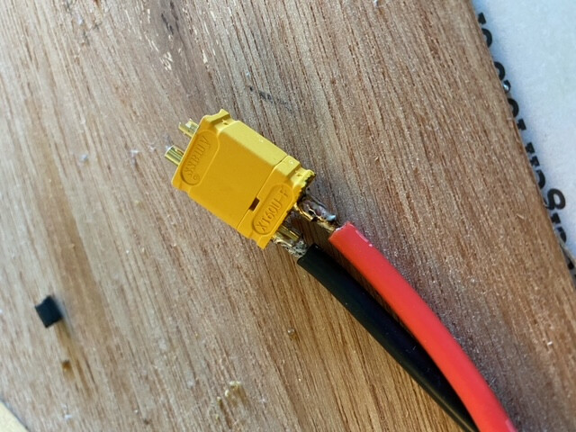
I’d be a little uncomfortable pushing high amps through that. It looks a bit discolored. A nice shiny finish is optimal. Are the wires pushed all the way down in the plug too?
It’ll likely work. Much better than your last one.
So this happened:
My uart bluetooth module stopped working after a firmware update so I’m completely up shit creek now!!!
You can see a bit of the rosin flux i guess. Is that a problem? I can push the wires just a little into the female connecter. The male connector has more space for it?
It appears that you have torn off some solder pads and circuit board trace copper…it’s essentially unrepairable IMO. Well, it could be repaired but probably at a cost higher than buying a new one.
I am really concerned about the, seemingly, complete lack of solder on the mounting legs. Were they not soldered to the board? If not that leaves the connector very susceptible to being ripped off, like what just happened. Those legs are there, and solderable, for a frakkin’ reason!
I think that is a huge design defect (if they weren’t soldered) or assembly issue. They have to solder the electrolytic caps in place as an extra assembly step…and maybe some connectors too?…so it would be easy to solder the USB shell too.
Oh…and add some frakkin’ RTV or epoxy around every vertical USB connector used in a product! The forces on the base are a lot greater for these vertical connectors. It pisses me off when a company sacrifices basic reliability to save a tiny bit of money…makes no sense.
Okay, got that out of my system…nothing to see…move along, move along…
That was the answer I was afraid of. The USB C port just became loose plugging it in normally on first go. I opened up to inspect and it was broken off. It may have come like that as I originally set this Torque6 ESC up with bluetooth but when I updated firmware the BLE module wouldn’t connect. Fuck!!
Is there a way to connect via bluetooth again. I was told it no longer worked when firmware update occurred because the settings default change to PPM, instead of UART and PPM. Is this true? Is there a PPM BLE that might connect?
Sorry, I don’t know.
No worries. Thanks for your detailed reply previously 

You could potentially SWD Prog the culprit VESC with your working VESC using an older version of software that defaults to control types of UART + PPM but that would leave you on an older version of the software. I’d talk to Torqueboards if you can get a hold of anyone there, seems like a manufacturing error.
Hey,
Is 5.2 vesc firmware compatible with 4.10 hardware ? From latest vesc tool i only get 5.0 and 5.1 listed as supported firmware.
I also tried installing the firmware from @b264 fork : bldc/build_all/410_o_411_o_412 at de1bee010866f5ca7e52109e18469b587b8f8d1a · variESC/bldc · GitHub
, but after installing and rebooting i’m still in 5.1 (and i get this annoying “old but mostly compatible firmware” message)
Yes, 5.2 VESC and 5.2 variESC are both compatible with 4.10 hardware although I doubt many folks are testing them together, but they are compatible.
If the firmware keeps reverting after a reboot, try uploading a bootloader.
Uploading the bootloader did the trick, thanks
You shouldn’t need this if you have a quality charger.
Use CANBUS to get yourself there.
XT60 type charger


