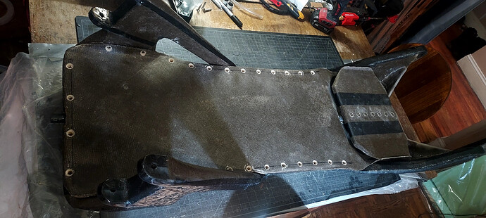
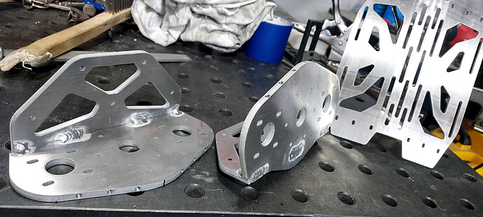
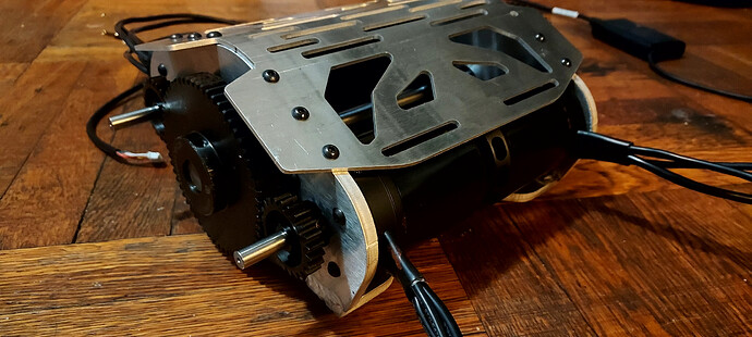
Rumor has it… He is the vacuum ![]()
he must suck really hard
Wow guys thanks for these vacuous comments.
I’m going to try and pressure you to be more helpful ![]()
https://www.amazon.com/gp/product/B00DYA21PU/ref=ox_sc_mini_detail?ie=UTF8&psc=1&smid=AFBMYHRQ9KU5H
Thanks! I’m using the cheapest possible setup lol. It’s one of these things running off a power supply that’s mounted under my table. They pull out about 2/3 of an atmosphere. 1/4" ID vinyl tubing is routed inside the bag and sealed with butyl tape, and half inch spiral cable wrap is used to distribute pressure inside the bag.
I get my ideas for builds by huffing all these epoxy fumes, it’s my darkest secret
Brilliant. Much more elegant then stacking cotton breather
I still use paper towels for breathing and absorbing over the parts themselves, but the cable wrap bridges the gap from the parts to the hose ![]() the spiral doesn’t crush closed under vacuum and close itself off either
the spiral doesn’t crush closed under vacuum and close itself off either
Part 2: The “JB” in “JB Weld” Stands For "Joining Batteries"
Step 1: Acquire unreasonable amount of P42A
Step 2: Acquire unreasonable amount of JB Weld (not sponsored (but it should be))
Can’t have enough fishpaper
Or P-groups. Or welds.
All the series connections are done with 10AWG flat braid, but I wanted to keep the connections at each end of the pack the same height as the rest, since this chassis is gonna be a little tight. So I tinned some 10AWG silicone wire, and cinched the braid around it with a thin wire twist…
…then dumped in more solder and trimmed with a flush cutter…
…and result can pack very flat.
And there’s the finished 18s9p pack! Forgot to take intermediate pictures. The series connections are 4x 10AWG, using both the top and bottom of the pack to spread out the current and avoid hot spots. The plates are 0.2x65mm nickel, and the p-groups are stacked with 3mm EVA foam between them to keep the packs flexible enough not to be stressed by the chassis flexing around in operation.
This is genius. Definitely stealing this.
Got any pics of this?
Genius
You can also open the braid tube up and stick the wire core inside!
I haven’t been in here for a while, looking really good! Part of me wishes i was fucking around with this kind of stuff myself, the other part be like naaaaahhhhhhhh
Of course, thanks!
Sorry, not without opening it up again, but it’s just nickel folded over and 2 flat braids, the bottom looks the same but narrower. The idea is that the current from the bottom row of cells doesn’t need to travel past the top row, it can go directly to the next p group.
That’s what’s going on! The braid is flared out into a tube on one end to insert the silicone wire.
Haha i see, nice work ![]() its a super neat joint
its a super neat joint
Work has been busy for the last couple weeks, and it probably won’t clear up till end of month. But i did some maintenance on my commuter board and broke the torsion shaft for this build out of the peel ply.
Since the ends of the layup got kind of bunched up, there was two or three millimeters of extra diameter to take down from them on top of the fact that the whole thing needed to be smoothed out a little. So I duct taped it to a hole saw and headed for the shower. Drywall sanding screens worked amazing for this, the removal rate was surprisingly good and i only went through one sheet.
Rate my setup.
She rotary grind on my torsion shaft until I shed abrasive microparticles
6/10
11/10 ![]()
Hallo, folks. I was out of town for work a lot last month and was feeling pretty burnt out for a while, but I’m starting to get back in the saddle. The past couple weeks I’ve been grinding (often literally) through the fitment issues I’ve been putting off.
I put a zillion holes and threaded inserts into the deck plate, since bolting that sucker on tight is how the frame will get its torsional stiffness. Still waiting on a hardware order to get screws of the right length. I also JB welded inserts into the torsion shaft to attach the footplate.
The torsion shaft came out slightly bowed, so I warmed it up until I was able to straighten it out, and it’s free spinning in its channel now. The plywood plate underneath the footplate also needed some gouging out since the height/thickness came out a few mm off of plan. It still needs bushings under the standing area, and front/rear thrust bearings to keep it in place under acceleration.
All the carbon forgings to this point didn’t have quite correct tolerances for the bearings and shafts, so I got 10mm precision ground steel bars to form exact fits for the 10mm shoulder bolts. Just a coat of wax, prep the inside of the bores, and a bit of epoxy. You can also see the deckplate getting its carbon pinstripes back there.
22mm precision steel bars are pricier, so I grabbed a length of 3/4" steel bar from the trash at work and printed a couple more mm of diameter for it. Sanded, then wrapped in packing tape, then waxed before used as another positive mold.
[~pop!~.mp3]

[~zzzzip!~.mp3]

At last, no slop! There’s a bunch more parts to forge for the steering mechanism, and before I start assembling the front fork and rear triangle, I need some laser cut metal parts to act as hardpoints for mounting the axles.
So all these parts will be real soon! Before this decade is out. Not because they are easy, but because I’m too dumb to know how much work and money a project will take before I sunk-cost-fallacy my way through it.
That’s some really weird looking carbon fiber
That’s a good point. Do you think it’s expired, should I send it back?


