It would make sense if you could use it instead of the CAN cable
Heyo,
Popping by to drop an update on the current situation on project and some other things.
So, the progress on automating the electrical testing further? The PCBs have arrived and I have assembled and hello world’d the single board that the HW is working as expected. I’m currently writing the specific testing scripts.
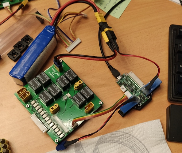
Here’s a pic with the single Lite that will be working as the tester’s “master” controller connected to the relay board’s GPIO-extender (MCP23017) via I2C, which then can control the relays on the board. There are normal mechanical relays for the “high-current” connections and then optp-mosfets for the 12S test battery cell sense connections. I will use the normal serial connection to the master tester to send commands and receive results.
The point of this relay board is to be able keep all the external sources/sinks connected to it and then disconnect and connect wanted external devices with the relays without messing about with plugging and unplugging connectors constantly.
Once I get this working, then if I could have a remotely controlled PSU I could automate the whole process pretty much completely… Well I’ll finish this automation step first and get the current boards tested, so I can start selling them.
Maybe soon, maybe not, there’s quite a lot on my table at the moment. If all things go well, I can probably get the tester working well enough next week to start working through the units that need testing.
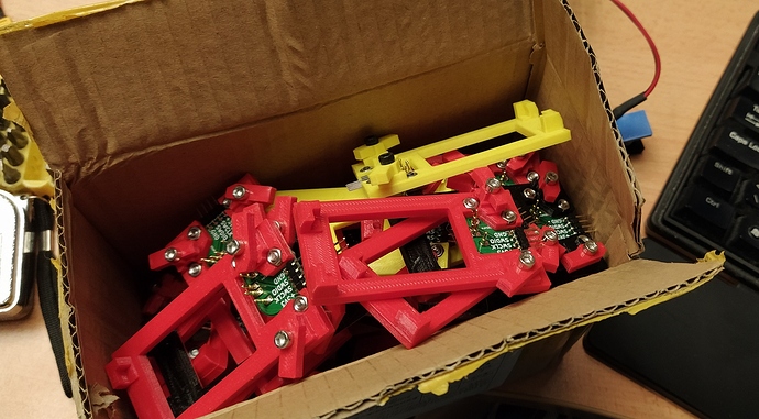
I also made a batch of these eZ-programming jigs for the Lite BMS’ that makes it super easy to connect a SWD-programmer to the unit thanks to the spring-loaded pogo pins that make contact with the test pads on the bottom of the PCB. Probably gonna be around 5-7€ ea. .
I’m back at the office after being laid off temporarily for a lack of customer projects last and this week and will be continuing my part-time schedule over there for the foreseeable future, so that eats into my time budget of what to do on my free time.
I’m currently working as the main hardware designer/enginerd for a very, very “particular” project.
I’ve also been having very interesting conversations with a colleague who has experience about motor controllers, welding machine power and control electronics and AC/DC-power supplies about AC/DC-converters and that I have had an interest for a personal first time project of making one. This was also in context to the current customer project, because there’s some power electronics design and topology related decisions that need to be done and working what is the most reasonable approach for the design goal.
Personally I’m interested in the AC/DC (wall power) power supplies with the intention of being able to design and build some custom high power battery chargers or PSUs, but the AC-side is pretty new to me and especially SMPS’ with transformers, also the deadly high voltages are another new thing that really haven’t appeared yet in own designs so far.
This then lead to a lot of conversation, topology research, looking at reference design and then in turn talking about the different topologies, particular implementations of the reference designs, how to size the transformer cores and so on. It went down a bit of a rabbit hole of conversation, but I’m now ordering a couple transformer cores and some bobbings, so I can start messing around with the transformer winding and design. Probably gonna start with the simpler topologies first and get a bit more comfortable with them first and operate them with lower voltages first for safety reasons.
Also been looking up some multi-phase DC/DC-converter ICs for the aforementioned customer project for better and higher power handling. Could be a simpler way to start getting in higher power chargers for say battery charging applications…
And of course, as winter is approaching (or was couple weeks ago) I have started to working on my winter light EV that I can tinker with and use during the winter, as my board will be in the storage. I’ve been calling it an ice speeder, because I was thinking of going and riding it on the frozen lakes, but we’ll have to see if we actually get any snow up here this year.
It’s being built on a drift trike chassis that I had impulse bought of off Ebay couple years ago and then realized I didn’t have time or motivation to really start building anything out of it.
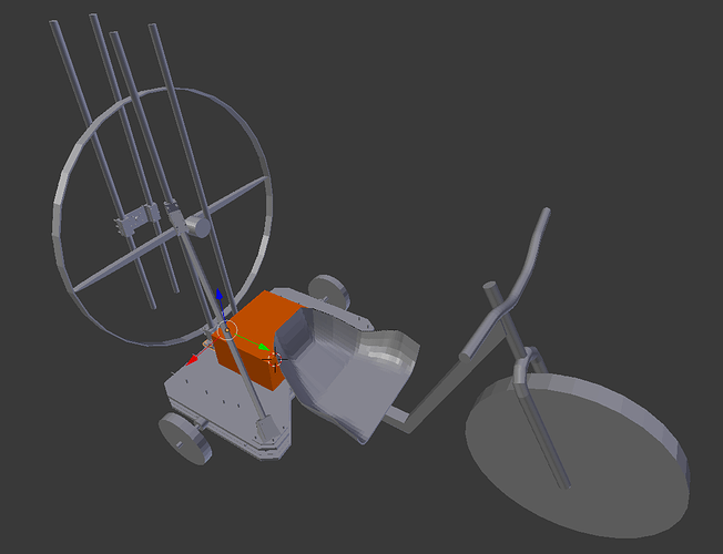
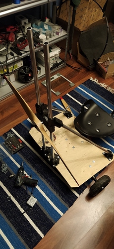
The thing is that I’ve had a couple of these bigger scale RC plane props unused on my shelf (20, 24, 28, 32"), so I wanted to see how much thrust they can actually produce. Hence the concept shown below was born.
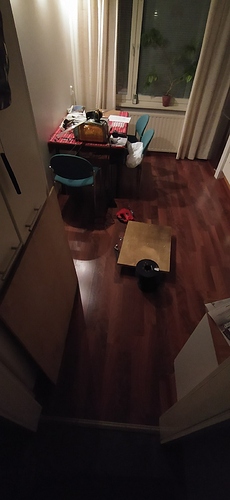
So, got some plywood, made some jigs, drew some lines on the plywood with the jig, cut some plywood on my kitchen floor (as you do).
I currently have the front supports prototyped and attached. The plywood bolts onto the same mounting holes on the chassis that the plastic step guard used.
Also did some actual spin-up tests with an old Maytech VESC 4.12 HW and a smaller placeholder motor with a 8mm axle diameter that the prop adapter can mount onto to see if there were any immediate problems with rigidity and vibration. The actual planned battery pack would be my new 12S7P 50E pack (that I will finish at some point, I need a bigger 3d-printer to make some exoskeleton for it…) and a motor from the esk8.
Short synapsis of my finnish speech in the video.
“Anything fun is always a little dangerous”
“It would want to start rolling forwards and that’s with this little tiny little test battery”
“I wonder what size the bodyparts are going to be that they will be fishing later from the lake…”
Now there is a quite real possibility that it won’t produce enough static thrust with reasonable power input to actually be usable and at that point the solution would be to switch to bigger diameter prop, which would produce more thrust for less input power AKA, I could actually get moving.
Backup plan would be to ditch the giant blender/hairdryer and use my esk8’s motors directly with the back wheels with an appropriate belt drivetrain. Been looking at some local hardware stores for nicely sized wheelbarrow wheels and make custom rims for them with correct bearings for the back axle.
Now,
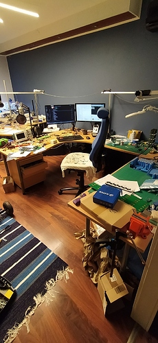
I must admit at this point that I am nearing the point of starting to seriously consider looking for a workshop, as even I must admit, the “living room” is starting to feel a little cramped… I wonder why 
maybe I can fit the table router in the corner…
But at least I looked pretty dapper for my big sister’s wedding that I was the driver for.
It can be used for GPIO/I2C/USART, but currently FW support is lacking for those functions, but they are available on the connected I/O.
You mean parallel as in "two 12S pack connected in parallel, both with their own Lite BMS’?
Yes, but FW support needs to be figured out how the CAN ID should be selected/configured and how to discover possibly multiple BMS’ on the CAN line.
The Lite supports officially 4-12S (3S does work, but the 3rd cell has roughly -10mV offset) and doesn’t have daisy-chaining support.
I’ve been doing concept design and some IC sourcing for a 6-18S standalone unit (like the Lite) based on the LTC6813 battery stack monitor IC, but it’s still in the concept phase. I need to get the Lite first into the “in production” phase, before starting make more versions of it.
Jan is correct, it’s not currently used for anything, but the pins can be used as GPIO, USART or I2C (the electrical testing controller uses the I2C from that connector to control an external I/O-extender on the relay board). It’s more of a “the HW behind the pins does support the following functions”
It’s more of a question of what kind of software handler would be smart for the I2C and USART.
Thank man for the reply
For the parallel that is correct, I meant 3-4 units each with its own BMS.
On the 18S, it is better to finish this project before starting the next. 
Im using 2 in parallel with no problem
What are the dimensions of the Lite model?
I’ve swear I’ve read this whole thread and didnt catch it other than it being small.
The space I have for it is pretty small, can barely fit a daly.
has anyone gotten this to work with a ubox yet?
So as of right now, cells can’t be monitored via metr unless its connected via CAN?
I’m just really trying to avoid using a giant ppm cable to connect my ESC to BMS
You dont use ppm cable to connect your esc to bms. You use a 4pin jst connector with 2 wires on can-l and can-h.
What benefit do you get apart for 1/2ing the balance time? In witch case Replacing the balance resistors with larger ones and a heatsink would do the same thing at a mutch lower cost.
Mostly because I cant run all the discharge current in one pcb. Can also run higher total charge current.
So there not fully paralleled there running 2 separate battery’s with only the main leads and charger paralleled?
In my mined this could case a issue with a p group getting over charged.
Say BMS A shuts down the charge as Battery A p group 6 is over voltage. BMS B is happy and keeps charging pack B. Pack B back feeds down the main terminals as it will want to keep both packs overall voltage = and keeps charging battery A with the over voltage group 6. The bleed resistor can dispose of 0.085A so if you charger is any bigger it will keep increasing the voltage in the over volt p group.
The software support for running multiple BMS’ in parallel from one charger is a bit complicated and tricky. There are quite a number of possible fault conditions that can happen and that can potentially be quite destructive depending on the scenario.
I think building the needed software support should be approached from the perspective of the potential fault conditions (potential fault conditions need to be recognized first) and then figure out what things the software needs to do, to be able to detect, prevent and correctly handle them when operating multiple parallel packs, regardless what the setup is.
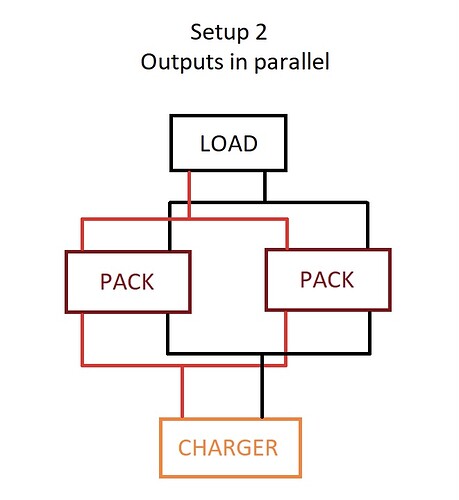
I think these are the two major possible setups or with bigger setups some combination of Setup 1 & 2.
The battery packs in the XL40 & XL50 boards We build are configured as this setup #2
Using on each 12S-3P pack a 12S-30A BMS for cell balance, charge and discharge and by sourcing cell from same production batch these tent not to drift.
The main thing will be how to implement your BMS since is not controlling the discharge ?
I can’t find where to buy this nor how much it cost? Can someone enlighten me?
Those should be available soon.
https://forum.esk8.news/t/flexibms-lite-flexible-configuration-bms-w-can-bus/8801/699?u=eretron
What are the risks of Setup 1 I figured if the packs have equal voltage, it would be safe.
Yes the pack voltages will be same, but there is a chance that one of the packs could have a cell that needs to be balanced out more before the pack can be continued to charge,
say for example cell voltages were 4,10:4,10:4,10:4,20 in a parallel 4S packs in one pack.
Let’s say other pack has 4,125:4,125:4,125:4,125,
both pack voltages would be 16,5V but the other pack has that single cell that is right on the upper limit, now it doesn’t matter if the other BMS terminates it’s own charging due to the high cell voltage, because the other BMS will keep charging as it sees it’s cell voltages still as OK, but due to the outputs being parallel’d together, it will also keep charging the other pack that has terminated it’s charging.
That’s why there needs to be talk between the parallel packs, as either one could have a reason to stop or not to start charging.
I wanted to get some input from everybody since I just bought a flexi bms lite.
My battery enclosure and esc enclosure are separate. I still want to be able to use the “smart” feature of this BMS. Beyond running a really long CAN BUS cable, can anybody think of any other options?
Also, has anybody tried running 12 amp charging with this BMS. I’d like to be able to charge at 1c, and for me that means 12 amps
Also what do I need to know about setting this up?
