I have two VESCs and DieBieMS interconnected via CAN-bus and it’s working fine. I suppose all of them have termination resistors. I believe it’s not too uncommon to connect four VESCs via CAN-bus for 4WD. Maybe this isn’t a problem?
Got it. Just my opinion.
Only possible CAN termination on the DieBieMS is the R69 resistor. I guess it has a 120R populated on it on the board?
I’m probably gonna get to design some military tech at work… Cool…
What about a solder joint ? Too big ?
EDIT : I used this tip for my SmartCharger

Unsoldered : no termination resistor connected
Soldered : 120R termination resistor connected
(I’m wondering about adding a transistor for a SW switch in a future version)
I left an uncovered trace at the other end of the termination resistor, so it’s connected by default. The trace can be cut, if it needs to be disconnected and there should be enough trace left, so you can solder bridge it later if need be.
On Focbox Unity i add a 4,7ohm 1w resistor on 5v canbus cable for 2 unity on 4wd to make it work safe
You put it on the 5V rail? Interesting…
I suppose the GND is already referenced via the battery packs themselves?
Then it would seem that the DieBieMS comes without CAN termination resistor. Probably works fine, because of short cable lengths.
Considering the following setup :
- Dual VESC 6 or similar
- DieBieMS
Then, both bus ends are both VESC as they embed a 220R termination resistor.
So the DieBieMS acts as a node on the bus.
That’s fine.
I think this resistor on the 5v of the the unity CAN connection is so that one switch can be used to power up both unitys via the can connector. I don’t this is related the the CAN operation in any way.
Yea you are right. Forgot about this
One question regarding the pcb design, and it’s not only for this creation, but for all the pcbs where one has chosen to solder a xt60/90 connector directly to the pcb itself.
Why not extending the pcb so that it gives mechanical support under the connectors? This would lessen the risk of connector breaking off the solder pads from vibrations as one could reinforce the xt60/90 to the pcb with glue. Seems a lot more reliable to me.
Does that mean that DieBieMS with only one VESC wouldn’t be ideal?
Usually there’s not a problem if termination isn’t exactly correct if there aren’t to many units on the same bus, try to keep the cables about the same length if not terminated correctly. I’ve had to terminate incorrectly sometime because the bus cables have had massive difference in lenght (not e-skate related)
Yes, in the industry we have to play with termination resistors (for DeviceNet networks, shitty field bus BTW).
Even if needed, sometimes it works without it.
The mystery of electronics.
In our eskate, we are below the meter length. That’s why it works even if it’s the mess with those resistors. 
I’ve been receiving multiple PMs from people interested in the project asking about reservations for boards and about when they would be possibly available for purchase. Here’s a clarification for the current timeline/schedule on the development.
There’s currently 2 things happening side-by-side. I’m setting up my company and I’m running the HW development for 0.5 iteration.
I will be making a couple hand assembled test boards for the 0.5, as I have done for all the earlier iterations as well. I’m not opening tester applications for these, but I will be sending a couple boards to a couple of FW developing testers. Once things look clear at least on my end (HW testing wise) the board will be ready for production batch, assuming everything looks good.
Alongside this I’ll be doing some company bureaucracy business of setting the new company up, making the name change and once the accounting is up and running I’ll start asking for quotes from multiple board fab houses and start filtering through them. Then I’ll negotiate with couple of them for the specifics of the build and see if they have any immediate feedback for the job. Usually the normal delivery times for a fab order are in the 4-8 weeks.
So when could I possible be ready to ship stuff? Hopefully somewhere around Q2 of this year. I’ll set up a webshop for selling. I have tinkered around with Squarespace sites in the past out of interest and set up some trial mock-up shops in there. The payment system is a bit more question mark at this point, as I think they use strip as the default payment processor, but I’ll have to see what kind of country support they have for Finland.
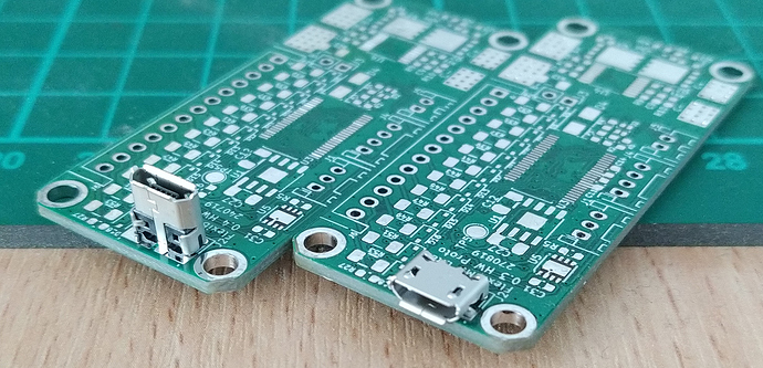
Closing up this post I’ll do a poll on which orientation of the micro USB-connector are you planning on getting. If the poll is clearly showing preference one or the other, then I may do some optimization of the PCB assembly order and get them to pick&place the more popular connector on most of the boards and get the rest without the USB connector soldered, so I can then based on demand hand solder the wanted one on them.
- Horizontal orientation
- Vertical orientation
0 voters
I appreciate the updates! Out of curiosity, is there a chance to see USB -C on these boards?
Why you all voting horizontal? Doesn’t it make more sense to plug in from the top while bms is installed in the board?
I voted horizontal because it would be much easier to protect from damage.
well my way of seeing this is that most board enclosures are longer more than higher so horizontal is better. I guess it all depends on your enclosure. Just depends how high your enclosure is and not everyone has a double stack.
imo of course


