Thanks!! I just couldn’t figure out what number I needed to fill in for 2 sensors 
Anyone knows name of that 16pin connector for balance wires and where to find it?
Würth electronik: 662016230822
Mouser, digikey, rs, etc…
1 Like
Its in the BoM on github, any electronics supply will do  mouser, farnell, digikey etc
1 Like
Never had to fiddle with any settings for it to power up when a charger is input, I only use push to start tho, might have something to do with it

(Powering via button still works ofc, pulse might be a global variable applicable to more than the push to start and button is only button)
Just had a look at my settings and It is set to Pulse as well. Strange, not a big issue, just strange.
Ah well for now I’ll just manually turn on the board each time.
Hey guys
I have a DieBieMS from 2nd batch (@Samau18), V.0.8. Today was the first time hooking it up.
As I power it on, crossed battery is shown on the OLED. I think because default is 12S, I run 10S.
After downloading drivers, I was able to connect in DieBieMS-Tool V0.30 over USB (on both macOS and Windows). Firmware is 3.38.
But thats all… It seems, that I am unable to send any configurations to the BMS. I can’t read the settings and also not write. I tried writing configurations with M-arrow-down, followed by Floppy Disk button (is that how you are supposed to?). But the status bar shows no signs of uploading. While connected over USB, „Bye“ is written on the Display, one solid green LED is on, the other one green blinking. No change of this pattern after hitting upload button.
Does anyone have an idea what could help? Thanks!
I solved it.
Apparently, FW 3.38 doesn’t allow DieBieMS-Tool to read/write. After FW-update AND triggering the bootloader manually via terminal (as described in https://electric-skateboard.builders/t/diy-6s-to-12s-bms-with-can-diebiems/2639/415) it all works now.
What a great Project! 
3 Likes
I have the same problem as ElCapitanoRosso but the thread didn`t fix it.
I recently shorted a balance wire in a bench test and damaged my DBMS, I’m hoping for some confirmation of what I think is wrong!

So I solder a bridge at the 0R location, and am getting better readings. But still not matching actual readings which are all ~3.50v for these four first groups.


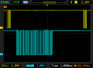
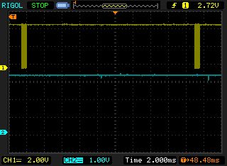
Has anyone experienced troubles with the UART communications dropping out? I have an ebike dashboard that polls the UART and the responses can be intermittent. On the scope you can see the request, but the DBMS doesn’t respond. Often when the oscilloscope shows noise from the motor controller on the lines (under throttle) the communications go dead. It feels like the DBMS UART code finds a frozen state since the request waveform looks good.
BMS_request_response.bmp (146.3 KB)
BMS_request_no_response.bmp (146.3 KB)
I am having trouble with the CAN bus on the DBMS. The VESCs plugged into the CAN connectors on the DBMS have no problem communicating, but the BMS does not show up in VESC Tool or on my Metr app (set to autodetect the DBMS). All devices are set to 500kbit/s throughput and VESC CAN style. Do I need to have “Emit stus over CAN” turned on? (it’s labeled as not implemented yet)
I am beginning to think I fried the CAN bus IC, but can’t pinpoint when it would have happened. Any tips to see if the ISO1050 CAN bus IC is alive?
Here is my mess of wires at the moment (not running the motors with these tiny wires, just getting the rest of the system set up first):


2 Likes
Out of the 4 Diebiems’s that I’ve tried. I’m having the same issue. All works fine other than being able to checks cell levels in apps. Sucks.
3 Likes
So you have had issues with no CAN bus communication with 4 DBMSs?
Yep. Tried with Metr and with FreeSK8 app. Everything else works fine other than that. Getting old unbolting an enclosure to check on my cells. It’s 2020 already. 
1 Like
Hi!
Can the VESC’s see each other?
Do you perhaps have a multi meter and can you check whether there is power on the isolated side of the ISO1050? ( PIN 5 and 8 ) (should be within 250mV of 5V, she is very strict):

With the ISO1050 you can also beep out whether the can wires connect everywhere, so all CAN Highs should be connected to each other and all CAN Lows.
1 Like
Danny, thanks for your response.
The VESCs have no issue seeing each other and the CAN highs and lows connect.
Between pin 1 and 4 I am seeing 3.25V
Between pin 5 and 8 I am seeing a floating value less than 100mV (it appears to slowly go up if I keep my meter on it)
Should I be seeing 5V on pin 1 and 5? Thanks for your help. Been sitting on this DBMS for a bit and am excited to finally be finishing up my board. I have no problem swapping out the ISO1050 if that appears to be the problem.
Yes with the minus of the multi meter on pin 5 and the positive on pin 8 you should see 5V. When this is absent the BMS cannot see the communication and cannot participate on the bus. Since the voltage should come from a VESC can you check whether it is present on the source VESC (between the GND and 5V of the source vesc)?