Hence my conclusion 
Wasn’t meant to be a negative comment to your post 
They should fit trampa base plates as well. Never tried, but the hole pattern looks like they will. Even with the holes for the springs. Think it’s the same base plate like on the old mbs spring trucks.
Thank you. I need reassurance. I posted twice yesterday and both were wrong information and now I feel incompetent😔
Then you learned two new things.
Well said Bill
I’ve seen this debated and it confuses me I have to read more to get a clear understanding of this.
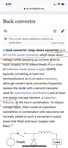
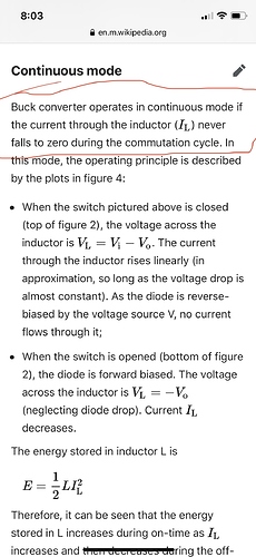
@drone001 the motor is the inductor that stores the energy as a magnetic field which allows the motor current to flow during the times the battery is disconnected from the circuit:
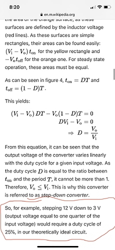
^you can see in the above diagram that since the current is flowing through the motor all the time, and from the battery only sometimes, the average current through the motor is higher than what is drawn from the battery (but at a lower voltage than the battery voltage depending on the % of time or duty cycle % that current is drawn from the battery — %50 duty means 50% battery voltage)
by varying the duty cycle, the motor current is controlled. the duty cycle required for a given motor current also depends on the speed of the rotor because the spinning magnets also produce a back emf voltage that works against the effective voltage, which is why constant motor current requires higher and higher duty cycle at higher and higher speeds. eventually you get to 100% duty (or 95% with vesc) which is full battery voltage and the rotor is turning its no load speed which means the back emf voltage nearly equals the battery voltage, so the motor can’t turn any faster and almost no current is flowing through the motor (only enough to overcome the bearing resistance). the motor can’t technically turn no load speed on its own because you’d have to spin it just a little bit faster with outside energy (to overcome the bearing resistance) to bring the motor current completely down to 0 which is true no load speed.
So as Andy said 40T are more 25a continuous than 30a.
if you really need those amps ( more power) then go for 30T but then your range will decrease since they are 3.5 Ah
The average Wh/km is at least 22Wh/km so if you want a more realistic range then change that. MTB usally consume in the 40-50Wh/km.
It totally depends on your riding style and road inclination and wheels but that is a good etimate already on what you will get.
no no no haha.
You can program the VESC to limit how much you want to charge you batteries (let say only 80%) and also the discharge limit ( let say 20%)
The more your limits are conservative the less range you will get but achieve a longer life span of the batteries.
You can, of course, push your batteries to the limit but then their life decreases.
You don’t need to worry about over discharging them. Unless you aren’t using your board for a few months and then need to charge them appropriately to avoid damaging them.
1 Charge cycle = 100% to 0%
So i what i like to do is get a bigger battery than i actually need so that i charge it less.
If you have a 10s2p and do 9km a day then you will likely need to charge every day. but if you get a 10s4p then maybe you only need to charge 4x a week and therefore increase battery life.
Hope this makes sense.
lol, i thought i was all slick with that remote when ir the esc that manages all that stuff 
very very clear yes, thank you for laying this out. considering the molicel P42A’s now, i mean it’s not a massive battery im building, so not too much monies more. funny i woke up this morning thinking it was gonna be a 30q build 
hi how do i mount lights and a gopro clone onto Matrix II trucks? or should I be mounting them to my board instead (that doesn’t make as much sense to me because of the roll the board experiences vs the yaw the trucks experience)
these looks like some good reading…thx
While I can’t speak on the actual mounting, I wouldn’t recommend putting a camera on your trucks… Most likely area to get hit by shit on the road.
I’m currently working on a 3d printed gopro mount that’ll clip onto a backpack strap.
how else can I prove to the city council how much shittier our roads are than described in their community improvement plan? i’m willing to sacrifice a clone camera; most folks spend a lot more on attorneys and lobbyists to get their way at public hearings
Alright, fair enough. I’d say 3d printed is the easiest way but idk what you have access to…
@drone001 the formulas in BLDC are:
Motor RPM / KV = BEMF V
((Batt V * Duty %) - BEMF V) / OHMs Winding Resistance = Motor Current
(Batt V * Duty%) * Motor Current = Electrical Wattage
Electrical Wattage / Batt V = Battery Current
(60 / (2 * pi * KV)) * Motor Current = Motor Torque Newton Meters
Motor Torque * Gear Reduction Ratio = Wheel Torque
Wheel Torque / Wheel Radius in Meters = Wheel Thrust in Newtons
^once the board is built, it can be shown that the wheel thrust depends entirely on the chosen duty cycle
*edit: fixed a couple typos
I don’t have access to a 3D printer. if i did, i don’t know if PLA would hold up. i might resort to buying @Boardnamics motor mount and screwing the go pro mount into one of the motor mount slots. I’m hoping money can buy me a cleaner solution than that. i really appreciate your brainstorming
Hmm… My only other idea would be to utilize the screws in the front of the truck or perhaps a modified axle or something… Honestly underside of deck would probably be easiest (though less ideal)


