Continuing the discussion on S-n curves and adding in shock loads. There is a fun bonus question at the end for anyone that makes it that far (or skips ahead). The first part ended with this S-n plot.
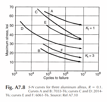
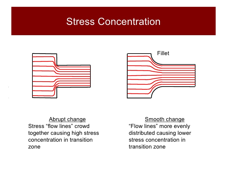
Notice that the curves are in two groups of three. The groups are labeled Kt = 1 and Kt = 3. Kt is the stress concentration factor. When there is a sudden change in the part geometry, such as a cutout, the stresses increase locally as they go by the reduced section. The sharper the transition, the higher the stress concentration. The red lines on this picture show what happens to the load. The load gets bunched together as it goes around the reduction in the cross section. That increases the local stress by the stress concentration factor. This is why it is better to have smooth transitions than abrupt ones in the cross section of your parts. The sharper the transition, the higher the stress concentration factor, and therefore the higher the stress under a given load. The stress is the vertical axis on our S-n curves.
The radius of curvature of the notch or transition determines how large the Kt is. The smaller the radius of curvature, the more abrupt the transition, and the higher the local stress. The radius of curvature at the edge of a crack can be very small, resulting in a very large local stress. As can be seen on the S-n curve, a large stress results in fewer cycles to failure.
Now let’s go all the way back to the equation of harmonic motion from the first part.
a = -((omega)^2) * A * (sin((omega) * t)
We can ignore the leading negative sign since this is a cyclic equation. The value of the sine of anything is always between -1 and 1. Since t is in this part of the equation this is the cyclic part. We can just assume that the value is 1. It is never larger than that. The first part of the equation is the only part that determines the maximum acceleration, and therefore the maximum load which equates to the maximum stress. The frequency squared times the amplitude (amplitude of the displacement of the oscillating mass). So the stress is most rapidly increased by increasing the frequency.
When we input shock loads to the system the majority of the input is at very high frequency. It seems instantaneous to us. When your board touches down off a curb that is a small shock load. When we want to test shock loads we apply a hammer test. We attach a weight on the end of a pendulum and let it swing from a certain height and strike the part under test. The metal-to-metal contact and the abrupt stop of the mass causes a large high frequency shock. The high frequency causes a high stress. The high stress combined with high frequency (therefore many cycles) causes rapid loss of fatigue life. The very sharp edge at the front of the growing crack increases the stress yet again due to the stress concentration factor.
I know. TLDR. Summary: avoid hitting your metal parts with hammers. You may not break the part as far as you can see at the moment, but you can rapidly deplete the available fatigue life (time until the part fails).
Back in the first paragraph of the first part I introduced the variables: “…the stiffness of the board, the environment it is ridden in, and the weight and style of the rider…the local effect of the cyclic loads, the material the component is made of, and the way it is processed…”. I believe I have discussed how they each fit with skating. Here is a summary of things that have been covered that can improve the service life of your components:
- Increase damping for a more stable ride – add plies of different materials to your deck
- Increase amplification for a carvey ride – match board stiffness with rider weight
- For metallics, machined from forging is better than machined from bar is better than machined from casting
- Make smooth rather than abrupt transitions in cross section
- Avoid using a metal hammer on metal parts
Absent any unexpected requests for a deeper discussion I will end this here. If you have specific questions you don’t want to post feel free to PM me. It would be very difficult for me to repay the help I have received here but I will do my best. I promised a bonus at the end:
- Bonus Point Question: why does shifting your weight forward deaden speed wobbles?
Give yourself a gold star if you answered that it changes the weight carried by the trucks, increasing the front and reducing the rear. The natural frequency is the square root of k over m. We set up our rear trucks stiffer than the front. The k is larger so the natural frequency is higher. The weight shift further reduces the front truck natural frequency and increases the rear truck natural frequency by changing the supported mass. It shifts the natural frequency of the trucks further apart, reducing amplification at the current primary high speed run input frequency causing the speed wobble. Shifting our weight to the rear of the board would narrow the frequency gap and increase amplification – bad juju.
