It’s been a while like that. I definitely can backtrack it to February. Thats when i told @janpom about the issue. Not sure if that’s the earliest case. Maybe we could add a psa or sticky information to somewhere, its been quite a few people with the issue.
4 Likes
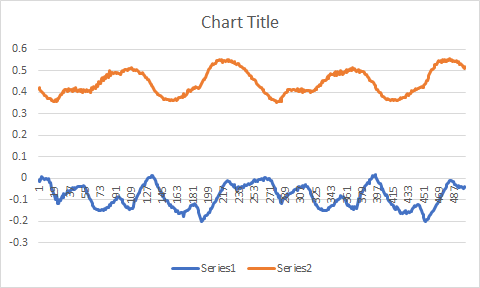
Was just messing with the HFI settings, whats the difference with the HFI samples? On the default of 16 I get whats shown on the right side of the picture and with 32 I get a tighter grouping like on the left. Are there different pros/cons of the sample rates? 
3 Likes
Yes the sample rate is always the same, so when you double the number of samples taken it also doubles the amount of latency in the sample. The algorithm runs a circular buffer where it always updates one of the samples each time step, so you always be 1/2 number samples * sampling frequency delayed from the true motor position. At slow speed this is not a big deal at all
(0.0001 seconds * 8 samples * 1000 ERPM )/ 60 seconds = 0.013 revolutions delay
But if you run 32 and set the transition at a higher ERPM 32 will start causing issues. The tradeoff is you get a bit better resolution, as you see with the decreased variance there. I think the best way to know what works best is just to test.
5 Likes
Today I had the following problem for the first time.
When trying to accelerate or brake, it felt as if I had a huge deadband and then suddenly it accelerated of brake very suddenly.
If it were not for the bindings I would have been thrown off the board multiple times.
I switched the vescs on and off multiple times, the same with the Wand remote. I also re-paired the wand.
The problem was solved when I re-run the input config wizard.
The board was working fine before that and I had not messed with any settings.
Trampa Vesc 6 running fw 4.2
Wand
6 Likes

The motor saliency information is embedded somewhere in here right? 
Any tips on how I can extract it?
Because if so, this may obviate the need to inject such large currents into the motor for HFI.
This waveform persists down to Q axis currents of 5A.
Wait, hold up, this is literally the approximate inductance for every single theta (ratiometrically).
Huh, well I just figured out a way to compute the inductance for every rotor position on the fly. Drive the motor in open-loop, either stall it completely or let it spin. Observe the Q axis waveform. Find inductance at theta = 0 by driving phase A high and phases B and C low. Use graph to determine ratio of inductances to every other rotor position.
The second graph also reveals that the PI current controllers inherently estimate the BEMF. I’ve found that at low currents, the resistance and inductance terms are rather small so errors in them end up being insignificant, so this explains why the VESC can track a motor despite having erroneous resistance and inductance measurements, and why performance degrades at higher currents.
Yes, the measurements are erroneous, two different RCL meters say so.
My official Trampa VESC 6 put a TB 6380 I have on hand as having a phase resistance of 24miliohms, RCL meters and my own controller put it at 21miliohms. VESC estimates a phase inductance of 13uH, RCL meters say 19uH, my controller says 17uH.
Open loop FOC can get up to 14k erpm unloaded, so that’s pretty neat.
Huh, flux linkage is also wrong, VESC says .004901, excel says .0045915, but I guess it’s close enough.
3 Likes
Yes! I just had this problem the other day! I thought I was imagining it because I just switched remotes, but the puck was working totally fine for the first few days before that started happening. I will try re-running app setup wizard. Thanks!
(VESC6 MK3, Hoyt puck, fw4.02, sensored FOC, 60a motor, 60a battery)
2 Likes
Need a bit of help, HFI is making the motor spas out. Was testing out the rain board and it was cogging at me and had no starting power on occasion, especially when the motor spins out on wet ground
10s, FSESC 4.12, 5065 140kv
@ZachTetra Follow this video very carefully
See if that helps. Doing this made it work much better for me than the defaults.
2 Likes
Hello everyone I just converted my unity to the vesc tool 5.1 and was trying to set up HFI on my motors and I set up my hobbysky 6374 190kv fine bu im unable to get my turnigy aerodrive 6374 192kv to set up properly. in order to get the red graph “narrow enough” is needs to be close to 26-30v (start voltage) and I can’t seem to get a working run and max voltage. any advice?
What was the biggest advantage with HFI on TBDDs compared to FOC with hall sensors. Curious to try but would like to get some info on possible advantages first.
Running TBDDs 75Kv with Unity, 12s, 60 motor amps / 120 battery amps.
Running well on current config but curious on HFI.
Do an experiment and try lowering Sensorless ERPM HFI: to like 700erpm. The default of 2000erpm seems to not work as well to me. Once you get rolling at all, however slowly, turn off HFI and use back EMF (regular sensorless mode), you can pump the amps as high as you want then.
1 Like
2000erpm is working fine one me.
2 Likes
1200 erpm is the sweet spot for my 80kv 80100. And under 10v for all the voltage settings
2 Likes
When you increase current levels from a stop, the lower erpm levels work better for me. At low currents, they are both the same. Except higher numbers buzz longer 
2 Likes
A post was split to a new topic: Staging for 502 testing
Just a callout, Thanks for this Benjamin and all involved. It’s been really helpful not to have to toggle between apps to switch between your trusted version ( 3.65 for me ) and newer firmware versions.
Also important was not accidentally encouraging people to update to latest versions when they weren’t yet trusted.
I’m very happy this new strategy was adopted.
3 Likes
who can gimme a hand with this. I havent used old vesc since i started a few years back and even then I was running dual focboxes solo on split ppm… so A how do i setup canbus nowadays on the new app? and Im a mac user so i cant plug in direct so was using a metr pro to do the setup. 1 vesc connected and updated fine and ran detection, now this is where im at on the 2nd vesc. please advise thanks!


Well… connect the canbus cable first… then from the master vesc (the one with the metr on) most of it just flies automatically after you do the motor detection.
If you want to setup something specific, press scan canbus and then activate. From that point all settings are to and from the vesc on the other end of the canbus cable.
For example: i have my bluetooth module on one side and uart remote on the other. To setup throttle curves i connect to canbus and then modify stuff
so as u see 1 connects, and the other only gives the shown screen and boots me back off. 1 vesc is updated to current firmware now and the other unknown firmware status… are u saying if i connect both with a canbus cable a) it wont fry the other vesc and b) would i be able to update the firmware via canbus? this doesnt sound possible but maybe who knows?
It seems like you have another problem here.
If when trying to connect directly to the esc you get that error, you most likely have a bust esc. Extremely common for flipsky.
One fix attempt is reflashing the bootloader through swd. Just search it on this forum, there’s plenty of cases specific to flipsky.
Or contacting the seller for a refund/replacement