Bandwidth! If we want to have a bunch of remotes in close proximity, 868Mhz only has a narrow legal band. Also in America it should be 915Mhz if I’m not mistaken, while 2.4 is mostly legal everywhere if using little amounts of power.
Just curious, have you found any problems with the sx1280 module? In all my testing RF performance was never an issue. And beware of IPEX connectors, they don’t like vibrations and tend to come off at the worst possible time.
Havent looked into this that much, but aren’t 800 and 900mhz bands less filled up comparing to 2.4ghz where you are competing with 100 desk printers in some urban areas?
Transceiver supports both 800mhz and 900mhz bands.
Ran out of warm days in autumn, but with 30km’s on clock at worst places it was stable. However I’m always striving for better product and have that paranoya that one day 2.4Ghz will be too clogged up for even lora remotes.
Smaller versions work on laptops just fine, true to be told, there is a case that keeps the connector in place, thus youre figthing more against corrosion than anything else. On other note, PCB antena is difficult but possible option.
That’s a related but different issue. LoRa is a spread spectrum modulation designed for noisy environments, and as such works well in this exact case. However if you run out of “channels” to place LoRa devices because your bandwidth is limited, you could have several remotes using LoRa on top of each other competing for airtime and that’s where problems can arise.
Not to mention that if you use an American band in the EU or vice-versa you are competing against cell towers and phones going full blast (in the W range, not mW) instead of printers.
TBS crossfire is a 900MHz protocol that’s very popular with fpv and it has switchable 868 and 915MHz mode, it’s very possible to get around that with a menu setting/switch. it also allows for 10 or more pilots flying at the same time, i bet it’s possible to use it
tho at the same time, having multiple DIY remote “brands” that can pop up, that end up also using 900MHz, would be a problem in a large group ride yaaaaaa
if you’re using a LoRa based chip, you can also check out FLRC modulation which allows better signal sensitivity, so it allows for more range,
or maybe in this case since we’re blasting RF into our baby juice generators which isnt that far, better SNR? (i dunno about that last part, it’s just me doin a 1 + 1 maybe = 2)
Yeah, I know, but I’ve also known a lot of FPV pilots that wondered why they were failsafing like crazy with their new crsf gear and it ended up being that they selected the wrong frequency out of ignorance or carelessness…
With esk8 the stakes are higher and I didn’t feel comfortable with that as a first option, also taking into account how well LoRa works @ 2.4GHz. At any rate it should be super easy to use another module running at different frequencies if anyone really wants/needs to. I just tried to select the safest design parameters by default!
Does anyone need atmegas, pcbs, parts? I have them all but the shell and battery and am in TX. I made my own remote, it’s fine detailed work that I don’t feel like doing for another 10 or so remotes. ~$40 for parts, ~$5-10 for shipping, pm to work it out!
The parts you would get:
PCB
2
Atmega 328P
2
SX1280 LoRa
2
USB C Charge Board
1
5v Booster
1
JST PH 2.0 Female
1
Magnets
2
Hall Sensor
2
Bearing
2
Vibration Motor
1
Brass Inserts
6
Screws
6
Wires
1
Springs
2
Last note, I opted for USB C instead of micro. This means there is an extra tab on the board that conflicts with the source design files.
Sorry, I’ve been kinda disconnected from the forum for some months now. Life happened (I’m a dad now!) and that + other unrelated projects took priority. Slowly getting back into esk8 now, but I started by making some batteries because my LiPos died during the winter
I should definitely mark this as v1.0 somewhere, because I can confidently say now the first version is both feature complete and thoroughly tested (about 8 remotes that I know of in the wild without issues in different environments and a few thousand kms between all of them). I still want to make some improvements in the future when/if I find the time:
If I ever have to order new PCBs, I have a 2.1 version with a stable voltage reference to improve the accuracy of the ADC readings (specially for the board battery measurements) and avoid having to calibrate every single receiver.
The more I look into it, the more complicated it looks, but a pairing algorithm to avoid baking anything into the firmware would be awesome
Better cases for printability and ergonomics…
Everyone and their dog is building HV boards these days, but the unfancy receiver only measures up to 12S voltage. So that.
I seem to always make the same list, but if I find the time it’s easier to tackle the most requested stuff if I find it in the latest comment xD
If you have built, plan to build or use one, please do share! I know a lot of people have been put off by the DIY nature of this project and the security implications, but it’s impossible for me to build and sell these given the baby, a full time job and my other hobbies/obligations. All I can promise is to try and make this even safer and easier to build with future revisions.
Yeah, life happened. Who would have thought rising a kid would take up THAT much time? Go figure.
At some point the stars aligned, sold my mountainboard to a friend…so I had the perfect excuse to build another one (post coming ). Started the build, ordered the parts and ended up having to build another Unfancy. Being strapped for time, with a perfectly functional and reliable project that I mostly consider done, documentation and even parts, what did I do? The only sensible thing, of course.
Starting from scratch
Here we go, baby. Strap in because this one is a doozy:
Fuck external power management boards from the deepest corners of aliexpress, 100% integrated power management it is. BMS with TRUE “ride and charge” functionality (https://www.microchip.com/en-us/product/MCP73871), high quality step up converter from Ti, nice step down to 3.3V for clean power.
100% magnetic trigger/thumbwheel (no more springs!). They’re also completely standalone and can be dissasembled from the main remote board for easy maintenance/replacement (I’ve broken a few shells on falls)
I ran out of IO to control the for LEDs so RGB it is! Did I mention they new board is TINY?
Calibration procedure and general baked in configuration sucked donkey’s ass, so…Integrated telemetry/config mode via captive web portal + AP mode it is (no one needs another app!)
Yes, I’m running fully fledged React with websockets on this thing! (never when riding, only in config mode!)
12-22S support on the receiver (selectable via solder jumpers)! Also there’s 2 PCBs now (TX and RX) since I crammed SO MUCH STUFF on the TX and didn’t want to increase the size. Also the TX is significantly more expensive than the RX (I really hope it evens out since there’s a lot less stuff to buy, the PCB does it all)
Dedicated AUX out on the RX (just 3.3V logic, no real power)
A stupid mistake I made when running the RGB LEDs. If you power them from 5V but run the data line on 3.3V logic, you’re technically out of spec. Most people get away with it, but my step up converter runs at 5.8V, so I have to add a zener diode that brings the LED power line back to 4.8V to be safe.
I’m now testing the RX code with a blank TX PCB before pulling the trigger on the next batch, but looking promising!
Next
Finalize HW and SW, design a prettier case (with two halves ), test test test test.
And finally
Why?
I know this is niche within a niche. I wasn’t 100% happy with the Unfancy, and it’s a damn shame some details kept it from the dream of a DIY reliable remote. Also because I like endless projects that live in the back of my mind rent free for months until I finally give up sleep to finish them.
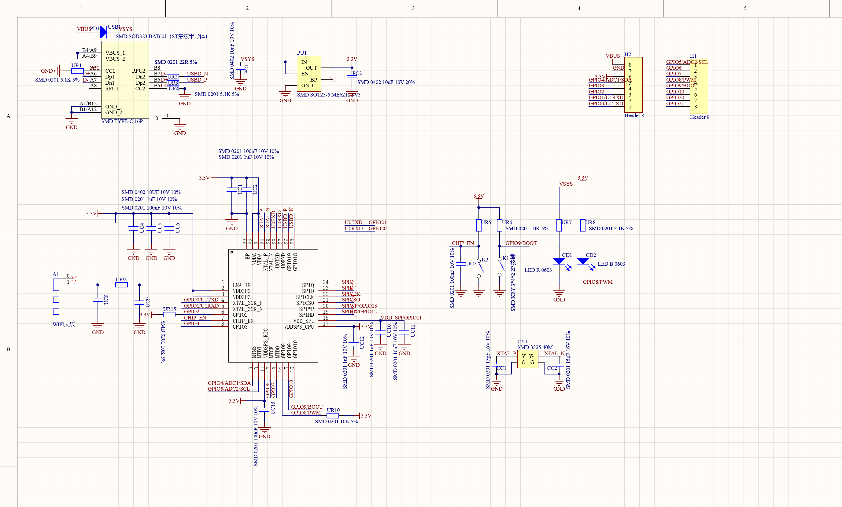
@tuckjohn@A-damW thank you guys! I knew of this fault, been using the ESP32C3 supermini for other projects for a while now
At any rate the integrated WiFi is only used for the captive portal when configuring the remote, LoRa is still used for the actual TX/RX communication. Someone smarter than me has actually done LoRa without semtech transceivers but there’s no way I’m risking that since the best part of the Unfancy is its reliability


