I am connecting the FTDI to the rx and using the serial monitor on my computer. The ftdi is set to 3.3v, and the tx is being run off the battery
Hello, where can I find a schematic of this? I would like to solder a pair without pcb’s
You can open the project in the /hardware folder using KiCAD which will include schematics, not only the PCB. However I wouldn’t recommend manually soldering all that’s required for it to work (and PCBs are probably one of the cheapest parts of the whole assembly).
I did it for the first tests just to see if it worked, but it is pretty easy to mess up the tiny pads on the LoRa module with the additional stress of manually soldering cables to it.
2 Likes
Can you show the traces for the TX? Maybe the problem is more obvious there.
1 Like
First of all, great project. I’m currently implementing it in my board in place of problematic mini remote and so far so good. I have small complains, but hopefully I will be able to address those later and maybe even help with improving the project and write some guides and such once I get more comfortable with it.
I got the remote working perfectly. However I do seem to encounter funny issue where RX wouldn’t turn on unless button is pressed. Did I missed something. Should RX be powered from the “+; - ; s” pins instead of 5v rail at the bottom?
2 Likes
Thanks a lot, I’m so glad you’re enjoying it! Please do share your feedback, is good for everyone.
Regarding the RX, you’re exactly right, it should be powered from the top pins which bypasses the on/off circuit only meant for the TX. I even remove the button from my RXs to make them slimmer.
2 Likes
Things from top of the list. I so far did dual trigger version, however esk8 buddy of mine did a single trigger version and encountered similar issues so most issues will apply to both remotes.

-
Marked in red, both of these parts are begging for support between base and cylindrical part, it can be both a fillet or support structure. Like this:
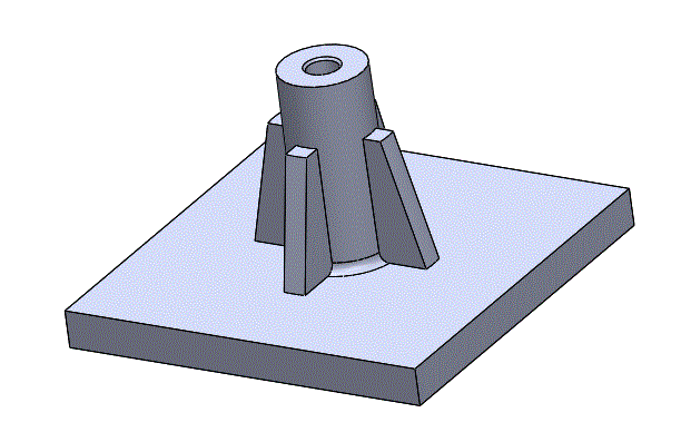
I first printed remote on a shittier printer with larger (0.19mm) layer height and both of these snapped off right in the part between remote base and extruded cylindrical section. I switched to Zortrax hips material and made reinforcement fillet with epoxy and it holds a lot better now. (Also I was a bit confused, you did add fillets for the sensor extrutions that carry way less force) -
Marked in blue, position of spring is not great, the way I believe spring should be placed is so that it always presses trigger against some sortof wall at 0 position, thus trigger will always return to the 0 calibrated value. What me and @CrazedMK encountered was that it would not always return to 0 position, instead not having enough leverege and sitting at ~5% duty cycle.
-
Instructions where a bit unclear which trigger goes to which sensor port, I did it other way around and I was wrong, I resoldered like it’s shown in picture and it worked. I retested later and yes the throttle and brake sensors aren’t interchangeable. The problem isn’t interchangability, but the schematic/description not saying what sensor goes where. I later used following pic you posted to determine correct connection.


- And allready afformentioned missing instruction on where power wires for remote should be connected on RX side. I know it may be somewhat obvious but I still found it confusing since the esk8 battery level wire has to be longer to reach other side of pcb unlike sensor wires.
I guess this is nitpick, but Ill play with ergonomics later to make hybrid design. Dual trigger is slightly too large for my hands and nunchuck design doesn’t go well with dual trigger design, it begs for some ‘‘finger indentations’’ or different shape where the thinnest part of U shape is further away from trigger finger. On single trigger you can use thumb/trigger finger as a support to keep remote in place. However on dual trigger version your fingers will naturally slide towards both triggers until they touch the throttle and locks it in place. (Analogy would be trying to hold a cone shape with one hand and keeping it in one place)
Quick reminder, as requested I’m including mostly critique in this post. Overall I love the project, my complaints are here only to make project even better.
EDIT: Oh yeah, almost forgot. Footprints for both, LoRa module and arduino should have wider ‘‘solder pads’’ to make hand soldering easier. The current ones are those annoying small pads that are PITA to do nice without soldering paste and hot air gun. There is also oddity with ground pads arround RF module having too much ground arround it thus making that specific pad more prone to potenially having cold solder joint doing handsoldering process. A fix would probably be having less copper near module or a regular 1cm trace going to ground pad.
8 Likes
Noted, I think you make very valid points. I’ve been meaning to revamp the dual trigger version a bit for a while, as I have actually switched over completely from thumbwheels…at least for the moment! A single trigger version is also in the works, but I’ve been swamped. At any rate, I’ll address your concerns here:
-
You’re right, I think I’m a little bit spoiled by my printer (spent a LOT of time during the pandemic dialing it in) and the particular brand of PETG I use is very flexible, so I haven’t had any troubles. The design can be improved a lot so it’s more forgiving and less dependant on the machine/plastic combo.
-
Regarding the “not returning to zero” issue, this is actually commented on the docs. Due to the very nature of the 3D printed mechanism it is recommended to lube it up a little bit so that it as an easier time moving until all the imperfections are sanded down due to use. At any rate you’re absolutely right, the trigger should have a flange to rest at “zero position” when not pressed, at the moment it can actually move the other way like a thumbwheel.
-
Will update the docs ASAP, you’re right that it’s not mentioned at all.
-
Yeah, the LoRa module is not that easy to solder…I actually enlarged the pads for V2, but clearly not enough. Bear in mind it is intended to be soldered using a hot air reflow station, but I do understand not everybody has one and I’ll try to make it easier to solder with a soldering iron (although there’s still the issue of space between pads and even if I make them longer, shorting them will also be easier). The GND pads are stitched to a ground plane to avoid loops and interference, that is not an easy fix short of cranking up the temps or using a more powerful soldering iron.
Thank you so much for the feedback and I’m glad you’re enjoying it!
8 Likes
Ok, wen’t for the first ride and it went flawlessly. 0 Cutouts, still have to visit couple of the bad places, but so far so good. While where at it I can finally do what Ive always wanted with mini remote:

Next up, figuring out if there is anything I can do with ergonomics. Thanks again for amazing work on this project @thunkar, hopefully Ill be able to chime in few contributions to project in winter. ![]()
Quick question, will the remotes with same channel and port numbers work with a single RX?
Awesome, love to hear it!
Yes, and vice-versa (you can control multiple boards with the same remote)
3 Likes
Started tinkering with ergonomics, here’s couple of conclusions ive found so far.
This is my old mini remote, on the left is what most would consider normal grip, however Ive found it troublesome as index finger is touching middle finger, it gets even worse with gloves. So what I’m using is grip style on the right where middle finger is pulling the trigger. Rest of the fingers are used for support similar to OSSR Bruce remote style. I wonder if anyone else has gript like this ![]()


Now I try to transfer same thinking on this remote. Again, on the left shows why I can’t do regular grip, index finger with trigger touches middle finger, when brake is pressed forces get disributed unevenly. On the right is style I use now, sortof works, even though most gripping work is done by the ring finger and pinky. Thumb is still in odd position and gives lot of paranoya as to not accidently nudge it during acceleration that would lead to sudden breaking force being applied.


This got me thinking, what if instead of brake being on top (and thumb being under stress) It would be placed on the side as a pushbutton that reads how far you have pushed the button. Only issue I see so far is ergonomics, it wouldn’t be pocket remote anymore.


Similar design has been around for decades on handheld battery drills for the reverse button.

Any ideas why this hasn’t been pursued yet? What would be safety reasons as to not have brake as a button on side?
2 Likes
I think your biggest issue here would be travel distance…I don’t think it would be very comfortable to have brakes so sensitive that are basically an on/off switch. Maybe the switch toggles the trigger between throttle and brakes? That could be interesting with sufficient ramping time to avoid instant faceplants ![]()
Fair point, workaround would be some clever mechanism similar to existing one that converts large swing to a small movement.
I talked with some local folks who did ergonomics for products, they pointed out that part of the trick to design good ergonomics is to look at fingers as vectors and carefully monitor their movement direction. As an example, when your palm is flat on surface, fingers are paralel to eachother, but when you pull them in grabing position they all point to some point afar like this:

Same goes with thumb that has pretty much most complex movement change.
I didn’t thought of this at first but it may work. Great idea! Disadvantages I see are that you have to place trigger back in 0 position to not have too aggressive of a brake. Or if you accidently push it then you get brake slam. On the other hand there are lot of advantages, same precise trigger/middle finger movement can be translated to breaking as well. AFAIK during esk8 racing you only accelerate or brake, no coasting. Lastly there is some space saved on remote for dual trigger version.
This idea is something that I see playing around more for sure.
1 Like
Soooo… a trigger remote? ![]()
Yes, but without mini remote drawbacks of locking your finger inside trigger and risking permanent acceleration during a fall or even mishandling when picking remote up.This used to be main argument against mini remote for many.
Im not sure if this has been considered but the idea came to mind and i figured it may be worth sharing.

To achieve a trigger mechanism like that it may be possible to use a linear potentiometer, with 3d printed part on top which is spring loaded?
Alternatively, using a longer linear potentiometer you could have a remote which is simply a long platform with a trigger that moves up/down with the thumb. Behind a defined zero position it causes braking and in front of it causes acceleration. Does that make sense?

Haha that’s pretty much bang on what i was thinking except spring loaded
The revel remote is a better version of this one

The spring tension on it is nice, my wife loves using this remote lol
2 Likes
Haven’t did much work on remote erognomics. However while working on other work project we came arround this module:
Same manufacturer but newer chip with slightly more power to antena. Only disadvantage is no PCB antenna, ipex and pcb solder only. We wrote and email and they where ready to sell them to us for 5.90$ + 30$ shipping. May order some samples and try making unfancy remote with said chip.
@thunkar Any reason why 2.4ghz was chosen over 868mhz on older remotes?
2 Likes