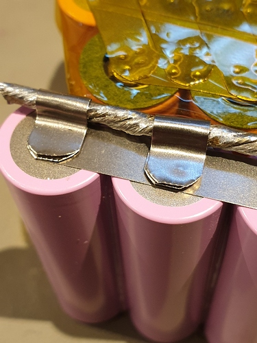
Where did you buy those ?
I’ve been thinking something like this. Solder first then weld
Actually you could weld the clips and solder the wire away from the batteries. Move the clips so they land in between cells so you can solder/weld them then have plenty of clearance to weld the base strip to cells
Yeah ofc, what about going through dual layers of nickel?, I have the Arduino spotwelder, been using it at 8ms pulses
Bottom and top finished, busbar made
Done for tonight
Tomorrow I’m gonna try to:
Put busbar on and weld it to both packs
Make and put battery leads on the pack
Find a box for the bms and epoxy it to the lid and make holes for everything
Connect the bms to the pack
Seal the monster box from the inside with silicone
And finish up the pack and seal it
It would be lovely if I could use the board on Monday with the new pack
Looks neat bro, although i do it like this and then fold it over, or solder on top of the nickel and then fold it down the side
Latest project:
Fitting as much Wh possible into a Tayto enclosure. With the latest BKB kits coming out I decided that I wanted to do one of my own, my own way. So I went ahead and ordered just the deck and enclosure knowing that the 10s3p that comes in the kit just wouldn’t please me, as well as the flipsky controller.
Enter 12s3p of Sanyo 20700b cells and Unity to divvy up the power. Not my typical style but it seemed there was enough room down the isles between P-groups to run balance lines without risk of damage. Still have to hook up a fused charge port and shrink it all. But this is where we are at.
520Wh vs. the standard 320Wh in BkB dual kit
All wiring oversized to maintain nice cool operation. 0.2x10mm nickel strip with dual 12awg series connections with tinned flat copper bus bars on either end. 10awg main leads
That looks like a perfect fit. Very nice. No way for 21700?
There’s no way 21700 would fit in this orientation. I’m gonna be getting pretty snug just trying to get the heat shrink on this one lol
That’s snug no room for any foam for vibration dampening then
Nice bed of silicone should do the trick
Bah, so much work, tracing the balance leads between layers of fish paper was hell and filling all gaps with silicone was the slowest progress, measured it out and everything is correctly wired, only had 14awg for the battery leads so that’s the reason I have two from each pole, but I think it should work and it may even be better, it was certainly easier to solder
Now I just have to wrap the pack and get something to put the bms in and drill the holes and all that
This pack has been 40 hours+ in the making, it’s good to see it coming to an end
Outstanding!
(That’s all I have to say about that…)

https://www.lithiumbatterypcb.com/product/14s-bluetooth-lithium-e-bike-battery-pcb-board-with-30a-constant-charge-and-discharge-current-2/
I have this one, 100A, should I wire it to use the same connection for charging and discharging or only for charging ?
Yeah I know, but I could always bypass it, I was just wondering wether I should go through the bms for discharging
@b264
@glyphiks
Or tag someone may know
I wouldn’t. But it’s up to you. Search ‘bypass bms’ for some other opinions.
100 amps is good enough. No need for a bypass on most applications. What’s the total output of the pack and what do you expect from it?


