Yea, the difference in the wire’s resistance for those setups will be tiny compared to the overall resistance of the spot welds, solder joints, connectors, and cell internal resistances.
Things like this are often done to minimize resistances as much as is practical so something like a single smaller set of pack main leads has a smaller effect on the pack’s overall resistance.
There might be plenty of room for connections inside the pack but very little room for routing parallel sets of main leads outside of the pack.
Main leads matching the gauge of the internal series connections are ideal but often don’t make much of a practical difference as long as the main leads are not overheating their insulation or the connector.
We can always run the numbers to see how different gauge and quantity choices actually affect the voltage sag of the pack.
I do it incase I need to use the pack (or a customer needs to) on a more powerful ESC, they can just use a thicker wire on the output and it won’t be internally bottlenecked
I search charger 20s lithium variable amps and variable maximum volt 80-84volt
Thx ![]()
Noted. The 3rd party bms and oem shells with left over esk8 cells have been brilliant.
I don’t want to hack dyson bms’ without balance capability.
=
I bought this wire - 10mm wide.
referring to this chart it looks like the braided copper can carry more current
For a 12s4p do I still need to use 2 strands of copper braided wire to connect each pack together? How about a 12s8p? or 18s6p?
next question - cant i just use a much bigger braided wire than needed to just do 1 wire per series connection?
I would do two per series connection just for more redundancy. It will also be much easier to solder two smaller ones than one big one.
That flat braid is roughly equivalent to 10AWG.
bought some 8mm to use instead, 10mm was a little hard to work with
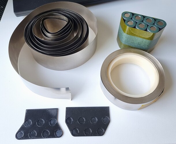
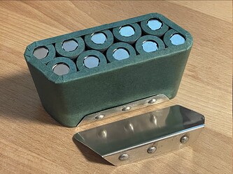
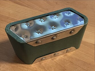
I am building a 14S7P battery out of LG M50LT cells. I have a large roll of 30mm wide 0.2mm nickel, but I figured it would be better to get some 50mm wide nickel in the same thickness. That way I don’t have to weld layers, and it’s easy to fold the nickel on top of the horizontal cells for soldering the series connections.
I ordered the 50mm wide stuff from NKON, and it passed the salt water test. No sparks when grinding with dremel. However, it is quite stiff. It is also a bit springy. The roll in the picture was wound tightly during shipping, and it sprung open like in the picture.
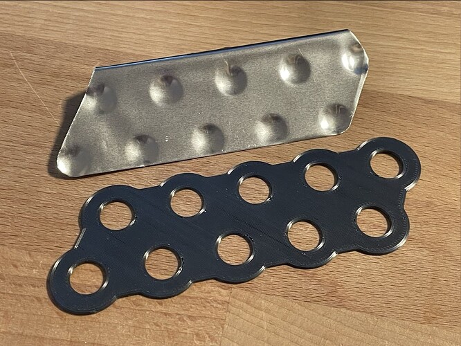
Because the top of the LG M50LT is recessed, I plan to use 3D printed guides to dent the nickel before welding. I can dent my 30mm wide nickel with a fingernail. With the 50mm wide, I need to apply a lot of pressure with a hard object such as a screwdriver to get it to form the dented shape. It’s not pretty.
What’s your take on this? Are some nickel strips just harder than others by default? Can it be that it’s not nickel? I think I can bend it easily enough to allow me to build the negative sides with it. I think that my plan A is to use the 50mm wide for the negatives, and two strips of 30mm wide for the positives. What do you think?
Yes. I believe it comes down to whether or not the nickel has been annealed.
Thanks! I’ll then proceed with the plan I outlined. Two strips of soft 30mm nickel for the positives since I can easily dent it to conform with the recessed cell tops, and a single strip of 50mm for the negatives.
I did a dumb and cut off the nicely conical points of my welding probes, what’s the best method to sharpen them back down?
I was thinking a chamfer bit in a drill. I can’t remove the copper probes so putting those in a drill is a no-go.
@glyphiks is totally correct, your nickel is just not annealed.
If you are interested in more info, I answered this same question in detail a while ago:
I just use a Dremel and shape it to however I want it
If I have popped welds can I just re-weld or do I have to dismantle, test, reassemble and use new nickel?
I’d just reweld if there are no lumps and bumps on the cells
Alright, how does this build look? My builder is awesome but hasn’t done more than 4-5 total packs. What does a good battery look like? All the solder joints seem solid. It fits perfectly snug in the enclosure.
Thoughts?
Looks like he’s let himself down with his choice of nickel.
Insulation isn’t covering the shoulders of the positive ends of the cells.
Wrapping it wouldn’t go astray either ![]()
Apart from that it looks great.
Edit: also, wtf is in the enclosure on the north side of group 11?
Edit 2: the outer most cells look like they only have like 3mm of nickel ![]() considering he hasn’t insulated the positive end shoulders properly, that is a big concern.
considering he hasn’t insulated the positive end shoulders properly, that is a big concern.
Edit 3: appears he hasn’t used rings on top of the cells either ![]()
The dude obviously has skills, but lacks knowledge in best practices.


