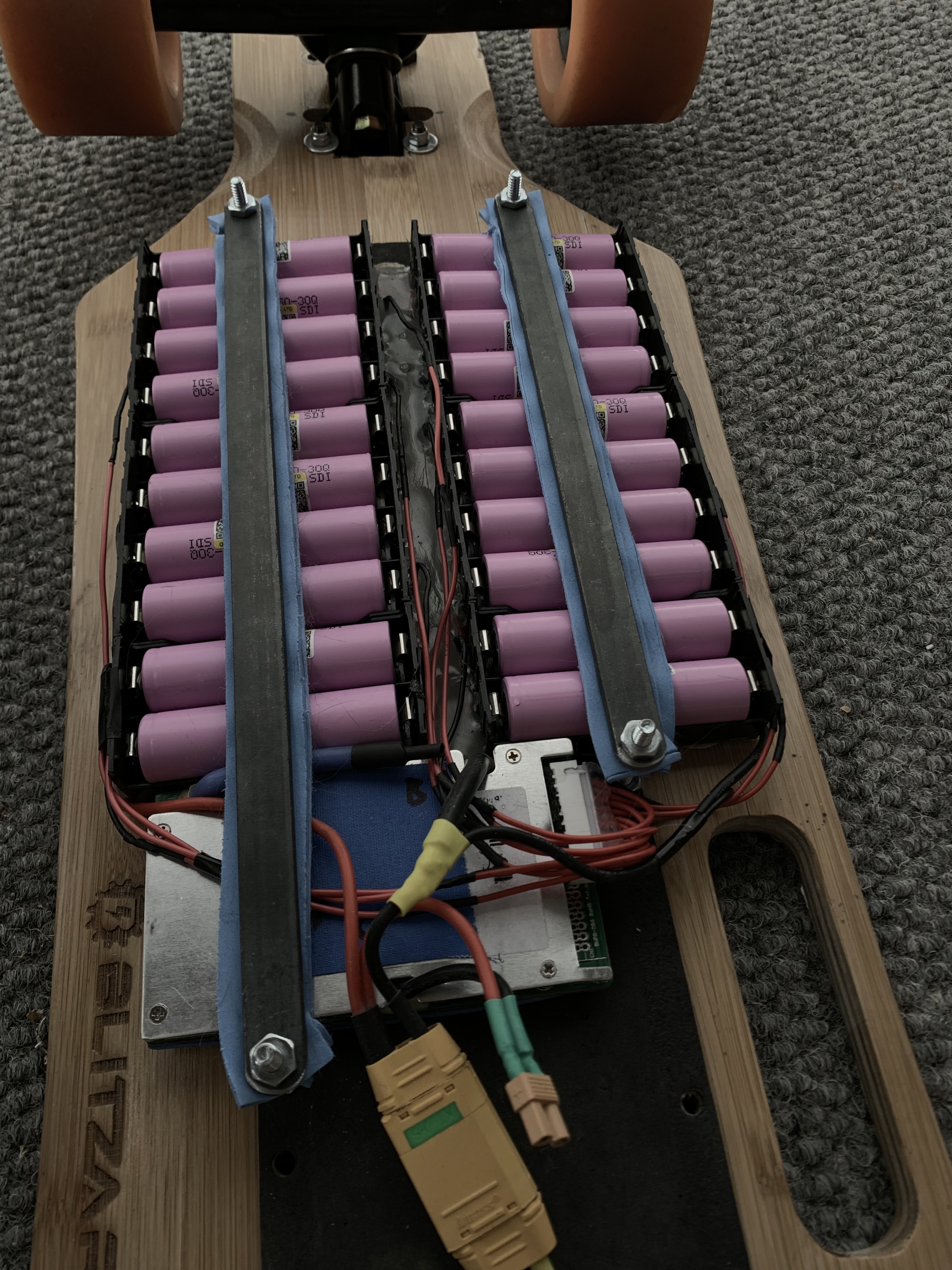
What do we think about this assembly style? ABS cell holders, 10 awg current carriers, cell > steel > solder > copper joints
Pros:
- Minimal risk of bridging p-packs
- shields underside of battery
- flexible (only when enclosure mounted)
- hella cheap ($20 for 10s4p) (only requires soldering iron)
- replaceable cells
- tested up to 10A
Cons:
- unknown amp capacity (tabs limit to maybe 20ish)
- 37% larger footprint over cells (no wires)
- only single stack
Notes:
- holders can be cut to make a smaller holder
- optimal configurations are 8s and 12s (6s, 7s, and 10s have leads come out an outer corner)
- use 4 slot holders (less cost and footprint per cell)
Procedure:
- buy holders, 10 awg, 22 awg, solder on eBay for $20ish
- wait 2 weeks for shipping

- fold the pins away
- tape holders for convenience
- make an XT90 pigtail (it’s the perfect width for the middle)
- strip sections of the 10 awg to match the tabs
- solder 10 awg to the top of the tabs (heavily tin both sides)*
- add more solder because it never hurts
- all the typical balance lead stuff
- insert your cells of choice
- shrink wrap the whole thing (190mm wide)
- drop it into your enclosure
*Work with the frame sideways so gravity doesn’t pull the solder over the contacts (it’s already a super tight fit)
These are my two battery packs made in this style (10s2p and 12s4p)