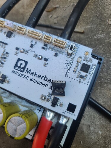
Oh what with the other pcb issues above its not looking good, we only have a ‘small sample size’ to base an opinion on and this is only a ‘revision A’ scenario for this controller so I’m keeping the faith a little longer.
What voltage where you running?
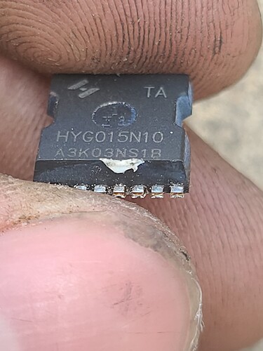
any idea of the part number of that mosfet
I was running 15s battery my maximun current was set to 100a was running 47 phase amps. I ordered the gate driver and new mosfets to see if its repairable. The logic still works can still talk to it though bluetooth.
Here is tthe mosfet p/n. I was accelerating when this happened. It blew a 600 amp fuse it surprised me
oh yes when mosfets short huge current flows, i’m running 80a fuses for testing and my bms is set to 80 too. i’ll order some spares…
new problem…
finally off the bench and on the street, pulled away slowly all good, decided to try a little faster, and yes a little faster…a very little…
vesc app shows 70-90 amps, watts shows 5-600, battery is about 75v…even the math doesnt work… its like 10x reality on amps, but the watts is true.
Bms app shows about 7a, and 500w which I trust to be right, performance doesnt even match acceleration to the 350w folding bike I have but I guess this is 3-4x as heavy.
20s/84v pack, mxus 3k turbo
on the mxus 3k turbo you can do a lot more. I push mine to 10kw 220A motor amps.
Vesc app show motor current, not battery current. Also, an mxus 3k will be a dog at that low amperage. 200-300a is where they shine
I’m sorry for not replying to your questions for so long, because as I said above, I need to perfect the circuit of the 84200HP and I have been busy with this work.
When I come back this time, I will reply to your questions and upload new schematics.
The model number of the field effect transistor is HYG015N10NS1TA. I have attached the specification sheet, please check it:
2203031730_HUAYI-HYG015N10NS1TA_C2979263.pdf (453.4 KB)
Hello, if the phase current is only 47A, the 84200HP can easily control it. The field effect transistor is the model HYG015N10NS1TA you have, 100V/380A.
I see signs of burnout in the gate driver? Is this a humid environment? If the environment is too humid, additional waterproofing treatment is required. The 84200HP does not have waterproofing treatment.
There is another issue that needs attention, which is very important, because it is the most common problem so far: please be sure to correctly configure the braking current and battery reverse current. These two parameters need to be determined according to the battery energy recovery performance. If If the configuration is too large and the current cannot be absorbed by the battery, it will easily break down the field effect transistor. If you use a switching power supply, it cannot handle the reverse current. Please be sure to configure the reverse current to 0.
oh my god, why didn’t i know these existed until now
well, atleast Makerbase sold me the original 75200s and now these Beasts
like dang mate, true phase sensing and real current amps
good job, ordered 2 now Lol
need these in my life, also cheap as hell, flopsky can put the 75200 pro v2’s where the sun doesn’t shine, might have “phase filters” but no real current sensing
too bad people know about the 75200 series and won’t find these controllers, should put 75200 better alternative in selling title
edit: question, for how much volts is the power SW pin rated or connect to which?
edit2: checked the schematic, it’s a pin for the STM so 3.3V, does it need to be pulled to gnd (internal pullup) or do i need to apply 3.3V?
So apart from my question how i could use or implement on/off switch
i would like to make a suggestion to maybe add a T section of copper bus going between the fets, down to the shunts and under the shunts a flat | section of bus bar before it goes into the phase wires for improved/reinforced current path
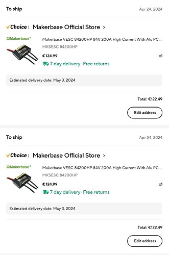
also since i ordered yesterday already i will get 2 broken esc from Aliexpress Makerbase official store? or will i get fixed ones?
“Hello, my ESC burned 2 MOSFETs out of nowhere. How can I easily remove them from the board? I can’t do it with hot air.”
phase amps, your motor current is too low for high torque, the current shown in Vesc tool is motor amps
you can even see that using duty cycle
duty cycle x phase amps = battery amps
“Hello, I didn’t quite understand the problem due to Google translation. I’m Portuguese from Portugal. I connected the VESC directly to the battery without overvoltage protection, could that be what caused it to burn?”
How can I desolder an SMD MOSFET?
its aluminium pcb so heating the whole thing would be the easiest, it conducts heat so well its almost impossible to only heat one part
apply smd flux aswell
on Aliexpress they sell small-ish 20x20cm reflow pcb “preheaters” which will get the pcb evenly up to temp and then you can come in with a hot air reflow station to desolder the fet
these are great if you need to do any smd work especially on alu pcbs
“I used this hot plate and a hairdryer, but the MOSFETs burned before I could remove them :(”
So mine arrived today, and the power switch on/off isn’t working properly
first time after applying power from battery, it’ll turn off the controller instantly when sw is pulled to gnd, that is good
However, after first switchoff and its powered back on fully (waited 20s to confirm), it seems to do nothing, it stays on, second time it turns off properly
idk why or what could cause that issue directly but that is concerning to say the least.
i don’t know if next revision could be made like more normal ebike controllers so you get separate battery in wire which is switched by one of those voltmeter switches or a screen, or atleast have that as an option via a switch?
incase you do that you definitely want more capacitance on the 12V buck in, but that’s not a big deal right?
i realize it won’t shutdown via vesc functions and won’t save the mileage to the chip, but i don’t care for that, i need a well working way to reliably turn the controllers on/off (i have 2) without having that issue possibly
I would suggest that the next version have more than 4 PCB mounting screws, ideally some in the middle and try to keep the PCBs flatter, the warp in this one means almost zero contact with the case. Also a bit more thermal paste but only after making better contact.
(Picture would go here but it won’t let me embed it, maybe a new user thing?)
And where the phase wires connect put some more of that copper bus bar under the wires to lift them up instead of just a giant blob of solder (unless they are already there but buried under the solder).


