Thanks. All noted.
2 Likes
Just ordered 6 tabs sets for 21700 battery. Cost was $42 shipped to USA using WINTERSALE2020 discount code. I’ll be making a 12S4P battery pack. It is going to be a 700Wh pack if I use samsung 40T, ooh the range!
Will start printing my compact modules soon and will update here.
7 Likes
@Agniusm all my tabs came cut for 4P when I ordered a 10s4p kit. I didn’t specify my setup so it’s my fault, but now looking for the best way to connect these 4P tabs to make a 2S4P end pack.

I assume I need to either join these 4P tabs or run a cable on the outside, correct?
1 Like
Yeah, run a cable on the outside. I have tried soldering on the inside and it’s not ideal or reliable.
2 Likes
I would just get some copper sheet, cut the strip drill couple holes and use heatshrink so insulate most. More fiddly but very compact.
I can’t visualize this all on the inside, is it something you have tried and have a picture?
Similar to this:

You only need to make U shape to run it outside from one side to the other.
3 Likes
Ok, but since I don’t have the copper strip and have 12 guage silicon wire, I can just use that like I’m planning to connect each pack to make the setup flexible instead of the bus bar, but will just need to run the length of the last pack.
@mishrasubhransu I understand you used braid copper instead of 12 gauge silicon because it was more flexible?
What about this braided copper case, would this work:
I was wondering why I couldn’t find the post, it was on the other forum.
So now that you’ve been using the board for awhile, any regrets of using Tin-plated copper braid over 12 guage silicone wire for this application?
1 Like
Nope, no issues.
2 Likes
How do I determine if the quality of the braided cable I linked above can handle the current?
I just saw in your other build you went with what looks like 12 AWG silicon. So which do you prefer, the silicon or the braided cable? If they both work great, fantastic.
I also noticed in this pic where you needed the long wire to connect the end packs like I’m going to have to do with mine.
They are both 10 awg wire if I remember correctly.
Since the wires are very short they can carry a lot more current. So don’t worry about it. One method needs soldering and other needs crimping. You can’t solder the braided wire properly though. It just makes it stiff.
1 Like
Ok, thanks for the feedback.
If anyone has used the included bus bars on a flexible deck, can you please speak up and report no issue with this setup connecting the modules that allow enough play when the board flexes.
It sure would make the connections unreliable or put undue stress on the 3D printed parts. Don’t risk it. And
2 Likes
Yeah, I’m leaning towards the braided cable, but @Agniusm mentioned in the other thread the bus bars design should facilitate the flex, so just curious if anyone used it with a flexible deck and how it’s held up.
I would test it. No major loss could accure. I would additionally use some thread lock. If its not good, its just few bus bars to swap out.
Does anyone got prusa mini 3d printer? Cute little thing for not too much money.
I want to make a 10s3p out of 2s3p modules. How many series tabs do I need to buy? Why would I go vented vs non vented? Thanks for the help
1 Like
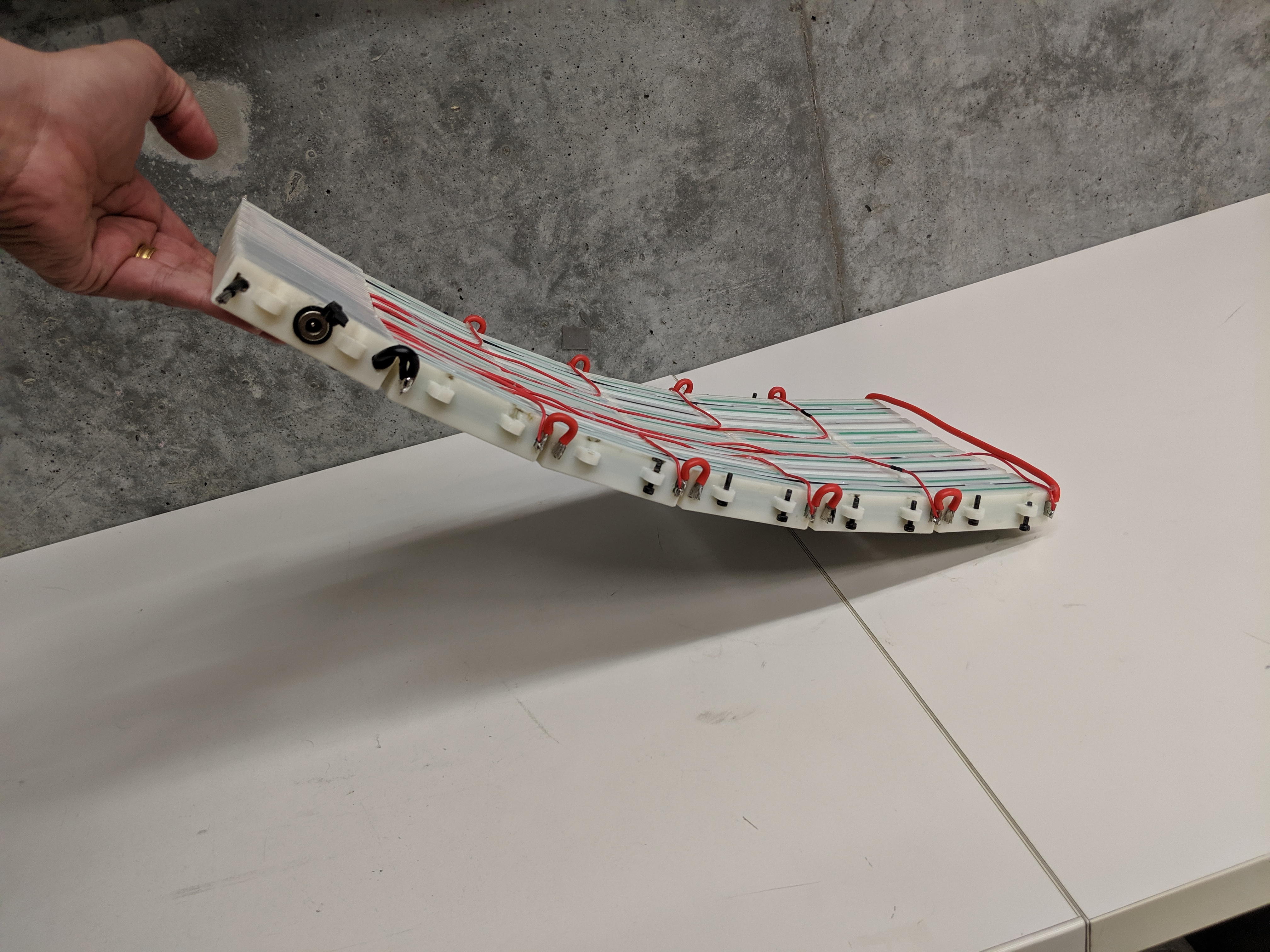
Big thanks to @mishrasubhransu, this is his NESE box. I scaled up his 2s4p module and it appears to work great.
We PM’ed about this before and at his suggestion, i scaled his box up 21/18 (166.666%) in the “battery diameter” dimensions (in my case, X and Z) and 70/65 (107.692% ) in the “battery length” dimensions (in my case, Y). Im going to tweak those numbers a bit for the next print, because this print sucked, but as a proof of concept it is good, and the dimensions work very close.
Side note, does anyone have a slicer profile for PETG that works good for them? I have a Creality CR-10s S5 and i have PLA completely dialed in (for functional prints, i dont know how anyone does those museum quality surface finishes), but PETG has been giving me fits.
P.S.: And of course a big thanks to @Agniusm for the tabs, and designing this whole battery system ![]()
1 Like
You are very welcome Ben.
It should be 70/65 because 18-650 and 21-700. I am guessing that’s why it was a bit tight along the length for you.
I just checked the pitch of the tabs and found out that @Agnius might be using the same scaling. Because from his models I know the pitch of 18650 is 18.3mm and measuring the 21700 tabs gives me a pitch of 18.35mm which is equal to 18.3*21/18.
1 Like
Whoops, my bad. I wrote the wrong numbers here, but when I was scaling them I did the math correct. I corrected my post, thanks for catching that!
2 Likes