From your pictrues can’t show the thread depth and we don’t know how did you measured the thread depth, but the depth couldn’t be just 2mm, even if our 6374 motor has 5mm.
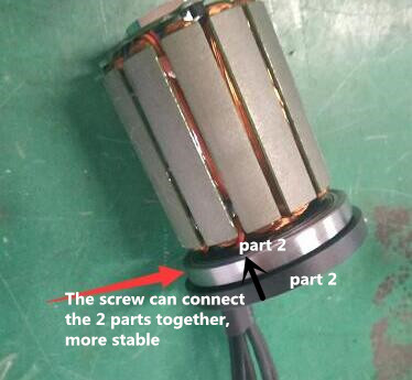
For this 6396 motor, there’s 2 parts thread to connect with screw as shown in the picture, one part is on the motor cover, the other part is below motor cover, 2 parts thread connect with one screw to make the connection more stable. (Sorry my English expression may not much clear, please see attached picture )
To meet most customers’s requirement, our 6396 motor added 44mm screw hole distance, and thread depth for 30mm screw hole distance is 11mm, for 44 mm screw hole distance is 8mm.
I mean it may SEem flimsy but with bolts, it is kind of weird how they work, the first thread takes about 38% of the load, and as you continue, it goes down from there, so usually the first 3 to 4 threads take most of the load. Since the metric bolts are pretty fine threaded, it might be a non- issue.
Over-torqueing is a whole different issue though and I think having more threads might help in that regard
I think my pictures are pretty clear, but if anyone else feels the same way as you, I’d welcome their feedback. The pictures show that for ‘part 1’ - the motor cover - there is no threading whatsoever. Would it be an idea for you to share a photo that shows the threading so that a fair comparison can be made?
I measured how much of the bolt went into the hole before it met the thread and then measured how much further it could be turned through the thread before I couldn’t turn it any further. Would you recommend a fairer, more appropriate way of doing so? I’d be happy to disassemble the motor to take a more accurate reading but I suspect that affect my warranty.
Now that you mention it I can see from your photos that the external piece of the motor housing is not threaded (or it looks like it may even be threaded but at a wider diameter) and what appears to be the inner-core of the bearing is the only threaded part.
Kind of seems like a really weird way of mounting the motors, if, this is how it is supposed to be mounted. Also, why does the diagram on maytech’s website for the 6396 show the M4 threads around a 44mm diameter but there is no 44mm holes to be seen?
Personally, my opinion is that for boards that flex you only want one axis of mounting that is perpindicular to the direction of flex.
So if the board is flexing in the Y direction (flexing about the X axis) then you should have a single point on Y with the mounting brackets along X. This way your board can flex freely under mounted enclosure without trying to flex the enclosure along with it. This should be better for rigid enclosures and be better for vibration dampening as well. I would just do your middle row of holes, and use some foam padding underneath to make it contact the board more uniformly.
Why do you need 3 holes? Two are enough to secure the enclosure and to prevent rotation.
And why does it need to be bushings at the ends? I would use strips of foam perpendicular to the direction of travel.
Damn those chains look sexy. Nice job on the enclosures as well, I’d love to see some other angles of the board. Something about the look of a crisp chain drive really turns my crankshaft