What doesn’t make ANY sense to me, however… Is that from what I thought I knew… There is no such thing as the system trying to “pull” more power through. If anything, it should be the opposite… Because the smaller wire comes right out of the battery itself, it should just potentially not supply enough power at all? I don’t think that has anything to do w the sparking / melting. The original manufacturer suggested they think there is a short in the controllers somewhere causing it. Which, of course, they have no advice on replacing. ![]()
Wish there was someone I could find in Charlotte to help me diagnose and create a strategy for this thing.
Hey … been contacting Oz and USA suppliers, both basically saying same thing -
Hi Colin,
Unfortunately with this old model, there is no more production of the CPU modules as the company that p[roduced this for us has closed down through Covid and is no longer in operation, so we dont even have the contact available to get original diagrams or componentry used… We dont have any alternative parts or options for these. If you have someone that is in your area that specialises in circuit boards, they may be able to investigate and repair what has been damaged or faulty.
Mine was one side front or rear burnt out … even worse lots of vids on Youtube showing new PSU’s getting slotted in.
Bit of a restriction we cant post images or Vids on here !
Yup. Same. They offered me a “deal” on a new one for the low low price of 3499.
Can u message me the video links? I have been hunting and hunting for some rebuild videos but haven’t been able to find anything. Are u saying u found some?
Still wating on photos depending on what it is makes a difrence. we talking about li ion thay have enouth power to Vaporise metal in some scenarios we use them to spot weld. A ESC caps have a huge inrush why we use anti spark connectors and switches.
So fare iv seem MT60 XT60 that are rated to 60A burst 30A continues.
1000w motor means nothing could be caped out at 10A (plug it in a VESC do a calibration VESC software will calculate the max amps for you to a fairly accurately.
Worst case 1000W / 42V 23A any good 10S1P with good cells can take that. No need for a huge 8p pack unless you want range.
Uploading: 20230802_131336.jpg…
This adapter was between the battery (t connector end) and the first xt60 you are zoomed in on which goes into the first controller. There is a switch on the controllers that is currently routed up the post to a controller on the handle bar. The sizzle happened on the xt60s. Both of them are equally charred now. Battery still seems ok and is showing ~38volts.
Did you verify polarity of that battery-to-controller connection first? Sure hope you have and are using a multimeter as you diagnose and work on this.
I’m pulling for you and @gscbuild to succeed in resurrecting these beasts and enjoy rallying around the golf course!
You’re in good hands here with some of the world’s foremost pev experts. Continue providing info - AND PHOTOS !
+1 my thought as well would be the polarity
Do you think this is a power switch? I would start by useing a multi meter seeing if rotating the switch makes and brakes polarity by switching it.
If it was plugged in switched on with no anti spark this could happen or the ESC could be shorted.
2nd I would try powering it up with a PSU (Most chargers are PSU’s should boot up check if there’s and very slowly add a small amount of throttle the wheels should turn. To mutch throat and to many amps will be demanded from the charger and it will drop the voltage or cut out but shouldn’t damage any thing. It the charger voltage drops as soon as it’s turned on id suspect the ESC is tost
Might want to reupload that ![]()
Polarity was double and triple checked, yes.
I am 90+% sure the ESC is toast as Darkie suggested. Nothing happened when I first plugged it in. And nothing happened after I turned on the switch… Smoke came out after the wheels rolled for just a split second. Now the display is dead (which is also where the power button is).
I am ordering a new VESC. Is the Flipsky dual 4.20 what I want??? Get the pro w the included switch? I had already installed a separate anti-static switch but not sure if that is now toast or not too?
you could risk it with a flipsky esc, good idea to order it on amazon with the cheap purchase protection in case it randomly blows up
This one is a better choice, yes? Just trying not to break the bank til i know what’s what. ![]()
Also, with one like this that has a switch included… I’m confused if I need an ADDITIONAL antispark switch as well?
Last, what remote would u recommend with this?
usually people with a dual VESC based esc like that DV4s will use a loop key switch for emergencies or if that internal switch fails.
You do not. Also, the circuitry in the new Makerx stuff isn’t an antispark circuit, it’s an ultra low power consumption sleep mode, as far as I know. So they’re unlikely to break.
Might as well just get a puck, it’s really the best you can get right now. I still want to recommend the vx4 but until they put in a better pot I can’t really do that
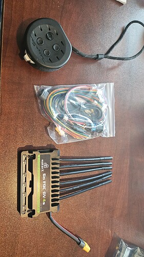
Ok guys… After a healthy wait, the stuff has arrived (hoyt st Puck and makerX Go FOC DV4s).
Since I still know basically nothing about the motors… How should I proceed in first testing / connecting them. I guess step one is to completely remove all the old controllers first?
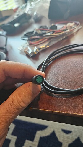
I’ll also need to figure out how to splice the tiny control wires into the round plug wire.
As that is what each motor accepts.
What other tips guys… I dont want to blow anything up. ![]()
“control wire”
“What the motor accepts”
confused
Each motor has 2 bundles of wire coming out of it. 1 is the typical 3 wire cluster of 12awg wires that connect to the esc, and the other are these tiny 5-wire cables which I assume also connect to the esc. Only on the esc, they are flat white connectors, whereas at the motor side they are these round plugs instead.
Ah ok those sound like just standard hall sensor wiring connectors.
All In One Schematic / Diagrams
you might find a good idea here.
if you can follow back to the esc from that 5 pin connector and figure out what wires are red/black that should be ~5V and the other 3 are the hall sensors. Seems like no 6th wire that is usually temp sensor, watch out for melting your motor with the VESC powa!!!
That’s what I mean… How do I make sure I don’t do that? ![]()
test run with like 15-25A ride it pretty hard uphill. Check motor temps with hand or laser temp gun. Adjust amps as needed.


