What’s new with hw v1?
Small improvements from the earlier 0.5-1 version, no changes to features. It’s more that I feel like the HW design is ready for official release, so I’m moving it’s HW revision number to 1.0 with the latest changes.
ah ok, where do you release, what do you release, and what are you goals for the project at this point?
Also talking about someone having a bad day. Not gonna mention the user, but they know who I’m talking about 
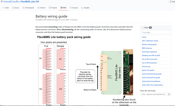
I have been in contact with a user that had problems with their new pack releasing the smoke from their BMS upon connecting the cell balance/sense connector. I asked about the steps in which they connected the battery terminal and balance connector and they did it in the correct order, first terminal connector and then balance connector → smoke. “Ok, can you measure the voltages on the battery pack terminals and balance/sense connector?”
“Sure.”
Couldn’t see anything wrong with the voltages, as they all increased in a linear order, indicating that there wasn’t a crossed/mixed balance wire in the loom, which I would have suspected first. Ok, maybe it was a bad unit, they can send the first one for free repairs… They luckily had another unit, so I said go ahead and connect that one and it also let out the smoke when the balance connector was connected again… What?.. This is not making sense, these units have been tested before shipping out, but we couldn’t find anything wrong with the voltage at the terminal or at the balance connector…
I mean I guess it’s possible that the two units were somehow faulty… I just can’t figure out how, at all. I’m completely flummoxed at this point. Luckily they had a friend they could get a loaner FlexiBMS from to try with. Ok, that should be a tested proven to work unit, likely.
Poof it went again upon the connection of the balance connector… So, they had said that they had built an earlier pack with a FlexiBMS in use, so I believed that they knew how to wire the pack and BMS correctly, but now all three units had blown on this new pack they were building. At this point, I was pretty convinced that it must be something to do with the new pack, but all the voltages looked alright… “Can you measure all the voltages against ground/B- from the battery pack and write them down?”
Next reply (paraphrasing):
“Oh S***, I realized that I had wired the balance connector the wrong way around”
Well that explains the smoke. So to clarify, they had accidentally populated the balance connector that instead of the bottom-of-stack cells being at the USB-connector end and “rising up” towards the other end, they were at the pack terminal end and the top-of-stack cells were connected to the USB-connector end. Funny thing was that they had wired their own first pack that was in their board and in use correctly, but made this mistake for the new pack.
Anyway, I currently have the 3 units on-hand and I’m repairing them and re-testing them before sending them pack. Unfortunately, as it was user error and the LTC6803 and the MCU seem to have popped from the units, which are the most expensive components. I’ll take the cost of the components, a little bit for the work (troubleshooting, reflow, repeating and retesting) and shipping them back to the user.
Check your wiring:
There are currently over 100 units of FlexiBMS out there in the world currently.
I release products (when I have something to sell) on my webshop finnkotronics.mycashflow.fi ,which is currently shut down/disabled, as I don’t have any units to sell, so I don’t want to keep running the monthly costs of the webshop, if I don’t have anything to sell. If the customer is a company and we’re talking about bigger batches, then I’ll do bulk discounts and invoice them directly.
I release my products and supporting products to my products.
My goal at the moment is to wrap my hands around STM’s manufacturing chief’s neck and gently ask them “Where are the chips!?” (JK). I’m currently limited by the global chip shortage and can’t therefore manufacture as many BMS units as I would like.
As soon as you have them available again I’m ripping two of them flexis out of your hands. 

Wanna come march to the STM’s offices with me ![]() ?
?
Always suspect a lot of confusion if you count from neg to pos or the wrong other way around.
Testing to prongs on the connector is dangeras procida but a very important one.
How exdpncive would it be to make a cheep pcb that could plug in and check for you? Some thing that could take any balance lead plunged in the wrong order with out showing the magi smoke. $10-15 I could see people buying if that hadf a couple of Battery’s to build
A red dot and a black dot on the PCB near the ends of the connector could help a whole lot.
So, you plug in the balance connector to this little device and it would show if the cell order is correct or wrong, or atleast if they are out of order?
Yes just no idea if I could be made in a way that’s not to exspncive that people would buy it. Just a idea of a product you could expand your range with.
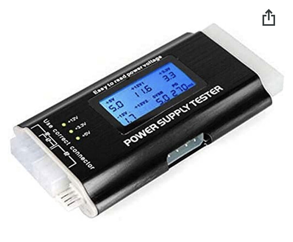
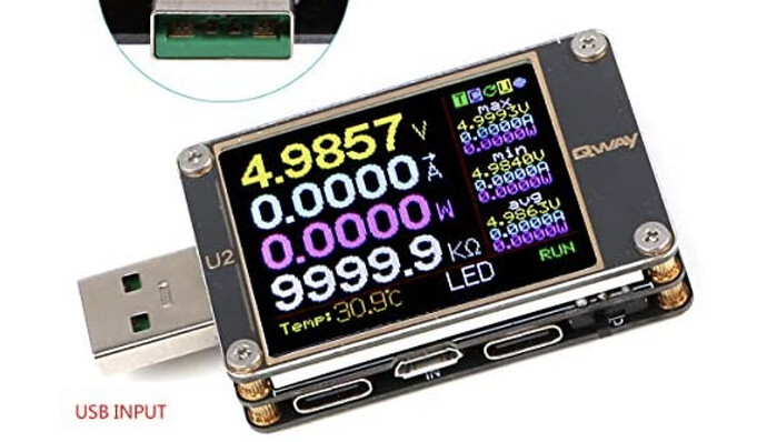
I have them for pc building to check PSU / amp draw on on cables and voltage stability.
If it show p group voltage it would help people who don’t have smart BMS as well. Unsure of how many different types of plugs are used in battery’s to how viable it would be
Sooo, what´s green green purple?
Green it’s charging and purple it’s a saved fault
Well usually that would be the case, but it´s not connected to a charger.
It´s a 12s but at 43V and looks like it´s throwing High Volt errors:
Fault Count:CELL1_HIGH_VOLT:1_CELL2_HIGH_VOLT:1_CELL3_HIGH_VOLT:1_CELL4_HIGH_VOLT:1_CELL5_HIGH_VOLT:1_CELL6_HIGH_VOLT:1_CELL7_HIGH_VOLT:1_CELL8_HIGH_VOLT:1_CELL9_HIGH_VOLT:1_CELL10_HIGH_VOLT:1_CELL11_HIGH_VOLT:1_CELL12_HIGH_VOLT:1_HIGH_BMS_TEMP:1_
Latched,faults:
$0=12 (Pack cell count; number of series cells in the battery pack, set to 0 to disable cell sensing, Uint)
$1=10000 (Max charging current; mA (milliAmps), maximum current allowed to flow to battery, Uint)
$2=300 (Charging termination current; mA (milliAmps), stop charging when current drops below this, Uint)
$3=2000 (Minimum cell voltage; mV (milliVolts), minimum allowed cell voltage, no charging allowed if cell voltage below this, Uint)
$4=4250 (Maximum cell voltage; mV (milliVolts), maximum allowed cell voltage, no charging allowed if cell voltage above this, Uint)
$5=10000 (Minimum charger voltage; mV (milliVolts), minimum allowed charger voltage, no charging allowed if charger voltage below this, Uint)
$6=55000 (Maximum charger voltage; mV (milliVolts), maximum allowed charger voltage, no charging allowed if charger voltage above this, Uint)
$7=7000 (Minimum pack voltage; mV (milliVolts), minimum allowed pack voltage, no charging allowed if pack voltage below this, Uint)
$8=52000 (Maximum pack voltage; mV (milliVolts), maximum allowed pack voltage, no charging allowed if pack voltage above this, Uint)
$9=4180 (Charging cell termination voltage; mV (milliVolts), don’t allow any cell to go above this voltage when charging, Uint)
$10=50400 (Charging pack termination voltage; mV (milliVolts), don’t allow pack to go above this voltage when charging, Uint)
$11=4150 (Cell balancing voltage; mV (milliVolts), allow balancing once a cell goes above this voltage, Uint)
$12=10 (Allowed difference between cell groups; mV (milliVolts), maximum allowed voltage difference between cell groups, balance if difference bigger, Uint)
$13=0 (Minimum external NTC thermistor temperature; K (Kelvin), set to 0 to disable, if enabled, the minimum temperature above which charging is allowed, Uint)
$14=0 (Maximum external NTC thermistor temperature; K (Kelvin), set to 0 to disable, if enabled, the maximum temperature below which charging is allowed, Uint)
$15=260 (Minimum PCB temperature; K (Kelvin), the minimum temperature above which charging is allowed, Uint)
$16=330 (Maximum PCB temperature; K (Kelvin), the maximum temperature below which charging is allowed, Uint)
$17=0 (0/1, allow cell balancing outside of charging, Boolean)
$18=30 (Fault wait time; s (seconds), How long to wait after fault state before trying to start charging again, Uint)
$19=1.0043 (Gain for Battery voltage ADC conversion, Float)
$20=0.0 (Offset for Battery voltage ADC conversion, Float)
$21=1.0104 (Gain for Charger voltage ADC conversion, Float)
$22=0.0 (Offset for Charger voltage ADC conversion, Float)
$23=1.0041 (Gain for Current sense ADC conversion, Float)
$24=0.0 (Offset for Current sense ADC conversion, Float)
$25=1.0000 (Gain for External NTC temperature probe conversion, Float)
$26=0.0 (Offset for External NTC temperature probe conversion, Float)
$27=1.0000 (Gain for Internal MCU temperature conversion, Float)
$28=0.0 (Offset for Internal MCU temperature conversion, Float)
$29=3380 (External NTC probe Beta-value; external NTC sensor’s beta value, Uint)
$30=16 (ADC’s oversampling setting; allowed values (1, 2, 4, 8, 16), Uint)
$31=24 (h (Hours), how long to stay in active mode, Uint)
$32=0 (0/1, force 5V regulator always on when battery connected, Boolean)
$33=3 (balancing temperature ratio, dynamically adjusts the max allowed balancing resistors based on BMS temperature, set to 0 to use static maximum, Uint)
$34=3800 (Storage discharge voltage; mV (milliVolts), if storage discharge enabled, then pack will be discharged to this voltage, Uint)
$35=0 (h (Hours), how long to wait from last CHARGING event to start discharging the pack to the storage voltage, set to 0 to disable, Uint)
$36=0 (0/1, CAN activity status LED tick, good for testing that the BMS is receiving CAN traffic, Boolean)
$37=10 (CAN ID number for this BMS unit, if using multi-BMS setups, all BMS’ need to have unique CAN ID, uint16_t)
$38=1 (0/1, if set to 1, keeps 5V regulator on if activeTimer is not expired even if USB, charger or Opto not active, Boolean)
$39=1 (h (Hours), up to how many hours a CAN-frame reception can extend activeTimer, set to 0 to disable, uint16_t)
$40=1 (1 or 0, can be used to allow CAN activity to wake-up the BMS from sleep, increases sleep mode quiescent current slightly, set to 0 to disable, boolean)
type in $R and looks for overvoltage values.
Awesome please update us if you manage to source more and make more. We need you and your product 
 really would like to support you
  I will be lookout for those chips
Those STM32L433CCY6TR have different soldering technic but aren’t they basically the same ? - I imagine it would not be too hard to change pcb to take this instead ?
There are over 250pcs stock now and the price is a lot cheaper than 3.5 vs like 6 for cc6
What does the state report show for the charger voltage when the charger is not connected? You can also reset the faults with $G, to get rid of that magenta color.
It’s a very involved PCB redesign and I’m pretty sure the place where I’m currently getting the PCBs made doesn’t have good enough production tolerances for the requirements for that tiny, dense package.
$2 alows me to set a static charge termination current witch is ok if you only ever use 1 charger. If I want to use a fast charge occasionally and still follow manufactures advice I would need to charge the settings on the fly that is possible through the metr pro but not ideal.
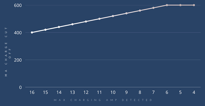
Is it possible for the flexi to calculate a table from 2 different charge amp and mA cut off and work out it’s cut off from the max charg ampage of that charge cycle?
Eg for a 4p q30 pack
Standard charge 1.5A X P group = 6A
Charge cut off 150mA X P group = 600mA
Fast charge 4A X P group = 16A
charge cut off 100mA X P group =400ma
So if you plugged in a 10a charger (max the flexi is rated for) it would set the cut off at 520mA automatically for that charge
So it´s not showing any faults with battery minus and balance cable connected. As soon as i connect battery plus, it´s blinking all colors like it should be and then goes into green green violett.
I connected the Flexi through USB and logged that behavior:
State:5374:5374:5374:5374:5374:5374:5374:5374:5374:5374:5374:5374:0-0-0:0-0-0:0-3-6:298:671:0:notCharging:
State:3586:3585:3586:3586:3586:3585:3586:3586:3586:3585:3585:3585:0-43057-43076:0-42476-42516:0-0-3:297:299:0:faultState:
State:3585:3585:3585:3586:3586:3585:3585:3586:3586:3585:3585:3585:42997-42997-43057:42455-42455-42496:0-0-0:297:299:0:faultState:
State:3585:3585:3585:3586:3586:3585:3585:3586:3586:3585:3585:3585:42997-43017-43037:42455-42455-42476:0-0-0:298:299:0:faultState:
State:3586:3585:3586:3586:3585:3586:3586:3585:3586:3586:3585:3585:42997-43017-43037:42435-42455-42476:0-0-0:298:299:0:faultState:
State:3586:3585:3585:3586:3586:3585:3586:3585:3586:3585:3586:3585:42978-42997-43017:42435-42455-42476:0-0-0:298:299:0:faultState:
The flexi does nothing in this stage, so no charging when i hook up some voltage, no displaying in the Metr App, nothing just blinking.
When i reset the fault with $G it stops blinking, but still not possible to do something.
I then disconnected everything, then connected batt minus, balance, batt plus and starting all over with the light show, then again green green violett.


