this cut makes the deck look super cool. vertically mounted motors isn’t something you see everyday!
11 March 2020
Ok, time to try not fuck up a £300 deck.
As anyone with CNC experience will tell you, the first problem is always work holding. Unfortunately the trampa deck is somewhat difficult to hold and laying flat the tips exceed the work height of my router.
the solution was to secure it to the bed using the truck mount holes. This had the added benefit that they could be used as a fixed reference point to keep everything square and in a known location.

What could go wrong?
I only had a single small carbon diamond endmill (designed for cutting composites) so i knew i only had one shot and if i broke the bit it would be game over.
Because of this i started with a very shallow adaptive clear to remove the bulk of the material.


And followed this with a contour on the vertical areas and a parallel toolpath to clean up the curves.

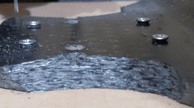
A little light finish with a fine sand paper and i was very happy with the result. (also really fucking itchy)

Finished both sides the same.

And both ends the same.

Perfect. This went way better than expected.
26 Likes
12 March 2020
Time for a dry test fit.

Started by properly assembling all 4 drives and meticulously lock-tighting everything that didn’t need to come apart again.

With the drives fully built up wit was time to get the hangers on the board.

Looking great. Quickly dug out some old 6.5" tyres to get a better feel of what it would look like with wheels on.

Start to realise how wide this is compared to my old board. With the street tread Its kinda got that buggy look with all the wheels right out on the corners

From here front you can see how easy it might be to add lights or bull bars to both ends.

At this point i was very tempted to change direction entirely, get an under mount enclosure made and turn this into a slick street carver.
But wait, The important question . . . hows the motor clearance?


22 Likes
14 March 2020
Got hold of some 8" tyres.

Starting to take the form of what i had been looking at for so long in CAD.

The look from above is so unique. Almost looks like direct drive.

Next to my current board you really start to notice the difference in stance.

Also seems to look so much more compact without the big motors hung out of the back.
One thing that’s interesting with this board is that running the motors above gives me the option to run to run the hangers reversed from heir normal orientation. This brings the ride height up a little and shortens the wheelbase and extra inch or two.
I have tried to estimate the center of mass for each truck, as well as the outer edges of the binding positions below to illustrate the differences from a traditional trampa board.

This shows the increased width and decreased length of this board.
Hopefully it also shows how the foot position is wider and the center of mass is closer to the foot. my hope is that this closeness between feet and COG give the rider a much greater feeling of control and much more authority over the ends of the board.
Whilst packing away i also noticed how much better the ground clearance is with the flipped hanger and mini drives.


27 Likes
Very nice and clear project!
23 March 2020
The day that shit stopped happening
Up till this point i had been using “Its Electric” event in Paris as an immovable deadline. i wanted to board finished far enough in advance that i could get comfortable on it and could ride it in the racing at this event.
little did i know that the whole world was about to grind to a halt.
On the 23rd or march the UK went into its first full lockdown.
Empty roads meant my ride time on my old board went way up and it was in desperate need of repairs and upgrades.
First was an top mount ESC case.
Then a top mount battery pack.
Then built another small board so that my gf could join the rides.
Made some CNC parts for other forum members.
More ESC case revisions.
More battery packs.
Then ITS ELECTRIC got cancelled. no more hard deadline and no more race events for the foreseeable future.
I got a beta 100D and decided to convert the daily to high voltage.
Made new Stormcore ESC Case.
By this point APEX was becoming a thing.
Saved a lonestar.
Started working on the airs.
Made an 18S pack.
Upgrades for the gf’s board.
designed the APEX NGB.
Customer repairs.
Switch main board to 18s.
Designed trampa conversion packs.
Prototype motors on 18s board.
Working on Apex Airs.
Building more trampa packs
Suddenly its its September and the 4WD is just sat collecting dust 

17 Likes
21 September 2020.
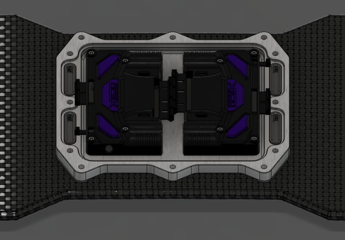
Finally found some time to start making parts for the center quad ESC case.
The plan was to use dual unities bolted to a single heatsink in a CNC case that sit under the battery. I would take what we learnt with previous ESC cases and bring cables in from the bottom to avoid needing any glands or silicone for waterproofing.

kind of arrived at this starting point with a plan to finish the top of the design when i had settled on a battery size. Also thought about pulling the center of the board back in to the standard trampa width just to save a little on the weight.

Cut the aluminum outer and bottom parts to check that everything fitted and there was enough room for cables. In hindsight it would have been far smarter to print these parts for this sort of test fit.

Everything fits well and it looks sleek on top of the deck.

23 Likes
25th Septemeber 2020
More distractions happen
First APEX AIR prototypes arrived.
Easing of restrictions.
Designed Trampa pack V2.
Quad Flying.
Apex ESC case V2.
Robogotchi Testing.
Started helping my friends get their 4wd builds caught up.
Airs Second Prototypes.
Customer Boards.
Lonestar Packs.
Predator Prototypes.
Apex Bullbars.
Batteries for friends.
Other Secret Projects.
DIY Remotes.
Suddenly were back round to MAY, its 2021, and my friends boards are starting to make quick progress.

If i don’t get a move on they will have finished building and be out having all the 4wd fun without me.
23 Likes
I have been waiting for this board to materialise for so long.
5 Likes
You and me both 

7 Likes
You know this is the only board that made me excited in so long (insert old man jokes here)
2 Likes
18 May 2021
Been thinking a lot about the ESC case design.
Kinda decided that im not fully sold on the previous square design. lots of wasted space and i don’t really want to route the cables into the deck like i previously planned.
Back to the drawing board.

Slightly different shape and less aggressive cuts to the board.

Same dual Xenith inside but this time with an integrated cable channel for waterproofing.


15 Likes
23 May 2021
Still not happy with the design. Start again.

This time its had a lot of weight removed. been designed to be cut from a single part rather than a separate base and wall. Also more space for phase cables, better 2 part cable seals and space for a lip seal around the whole top edge.
The design uses a these thin spacers on the outer edges between the case and the deck to continue to allow some deck flex.

Relatively happy with things this time around (and learning from my previous mistake) i decided to print This part to to test fit and check everything.

Yep, happy with that. Time to make it real.

This kind of machining is on the limits of what my CNC is capable off so had to take it slow.

Roughed and finished the inside.

Then the holes and out contour.
I some small tabs to keep the part secure knowing that i would be able to machine these away when doing the operations on the backside.
15 Likes
31 may 2021
Got the parted mounted back in the CNC and realigned for doing the reverse opperations.

Not the cleanest of cuts but at least i didn’t fuck it up this far in.

Little bit of a clean and it looks fantastic

This is the most complex and time consuming aluminum part ive made to date at home.
Also started thinking about the lid.

21 Likes
1 June 2021
upon realising that i didn’t have a cable entry point for power  i decided to revisit the cable entry points.

New design with simpler assembly and less parts. Also they split in some places to facilitate replacing motors without having to cut and re-pin the sensor cables.
Also started pondering the cable routing

18 Likes
2 June 2021
Still not happy wit those cable exits.

Another go, this time with a single large opening inside that means sensor plugs and bullet connectors can pass through evenly. Also a curved lip on the inside to reduce any cable wear.
17 Likes
5 June 2021
Made up a dual power adapter to power both unities.

Also fully stripped them down and extended all the phase cables.

Also realised what a nightmare all the cables were going to become so designed this quick little cable clip to keep motor cables under control.

And some tiny little cable spacers

Printed them out

And started the tidying.

The clips keep cable spaced evenly and cleanly.

A little heat shrink then keep all this secured.

Finally the cable clip bolts down to the truck bolts and keeps everything in place.

Way better than i expected.

32 Likes
Damn man, the attention to detail is 
Wish I had your patience.
6 Likes
Loving the clean execution and thought process behind it. A true evolution indeed.

12 Likes
6 June 2021
Seemed like the best solution for keeping the cables out of the way would be to run them under some printed foot pads, rather than having to route them into the deck as i had previously planned.

The pads feature a series of bolting points as well as space for 9 cables to run underneath (6 phase, 2 sensor and a space for lights or accessories).

19 Likes