I have the all metal and I’m using the TH3d firmware filament change every time. Never had an issue at all, and the ends of the filament come out so clean that I don’t have to trim it anymore before I want to reinsert again. Only thing is that I have to “purge” twice to get to extrude evenly, but I am too lazy to edit the firmware to make it extrude for longer during a purge.
I think I might have got a bad batch of alloy 910. It wasn’t sealed. When I’m printing with it, it bends inside the direct drive … is way too flexible.
I’ll order another one and see if because this roll got way too much moisture.
Wait, there is something wrong. Why would it bend? Even ninjaflex can be printed nicely with this setup. In fact, this is one of the best setups to print flexible.
Did you use a PTFE tube sticking out of the v6 radiator part? This is also necessary for all metal hotend.
Don’t worry about it being sealed. Just put it in oven at low temp 65C and it will dry out. Just make sure it’s protected from direct heat from the coil. And then store it in a dry box with silica gel(good cat litter)
There must be something wrong with my setup then. The little pipe that goes between radiator and hotend gets clogged. I have to drill the crap out of it 
That’s exactly why I asked not to pull the filament back. Just use motion->1mm->extruder to extrude about 100mm of filament. Before you do that, cut the old filament on the top and align the new filament with it, then extrude 100mm of filament. Bam! Done.
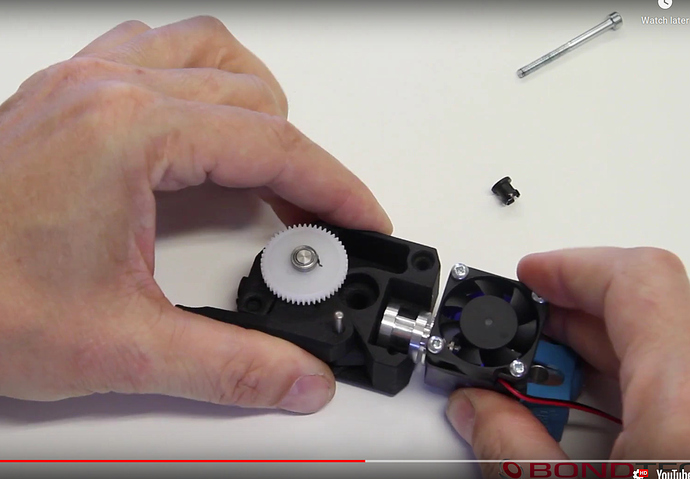
Man did you also have problem to assemble the hotend in the mount? The pocket is good but the all thing is shifted of like 2-3mm to the right and so no way I can get it in. I am also try to remove plastic but it’s al lot of material and I can not get it in. Problem that I have already unmount all the stock parts so can not print another one after fixing the step file.
Maybe in the picture is not clear but the hotend finds itself 2-3 mm off set from the pocket.
It’s ok I got it work. Dremel and make a new pocket and that’s it.
Yes I know thst you don’t have to use the bowden clip. It won’t literally fit in the BMG with it
Can you show where you had to remove material from, so I can fix that?
Also @mishrasubhransu did you have the same issue?
Yup! Guys that was my issue. The damn clip! You have to remove it. That’s why mine was getting stuck all time.
Also … yep, I had to dreemel it as well. Sorry I forgot to mention it
i will post it later…I am getting crazy with all this small bolts  Almost done btw
Remember to put them before mounting everything. It’s super snug but they fit precisely. IIIRC one hole for the hotend fan is too small so the bolt might not fit.
Yeh I had to unmount half to insert the M3 nuts I forgot 
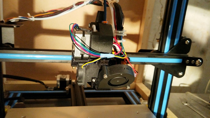
Anyhow here it is. I still have to update the firmware. I hope I connected the bltouch to the right pins.
Do you set the extruder to 415 and then made the calibration or did you leave it like that?
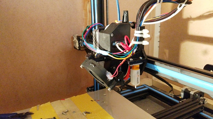
I used a bowden tube to keep the wires under tension otherwise they could bend and on tall prints potentially touch the print. I should make something to keep the wires up, maybe usong a skypass holder. The one with the spring 
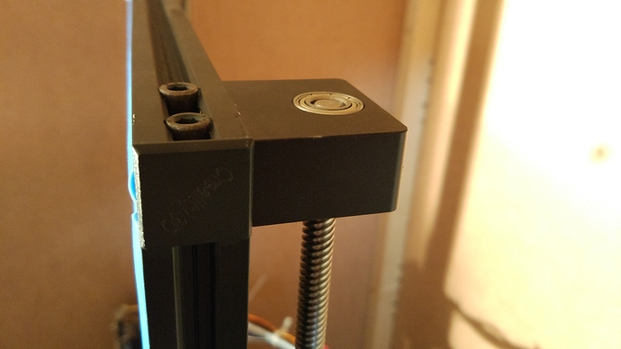
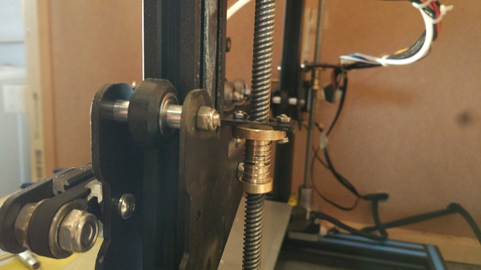
I also added the antibacklash nuts since the Z axis is way heavier now. Also replace the Z plate with aluminium one and snug fit bearings.
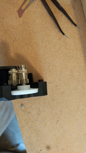
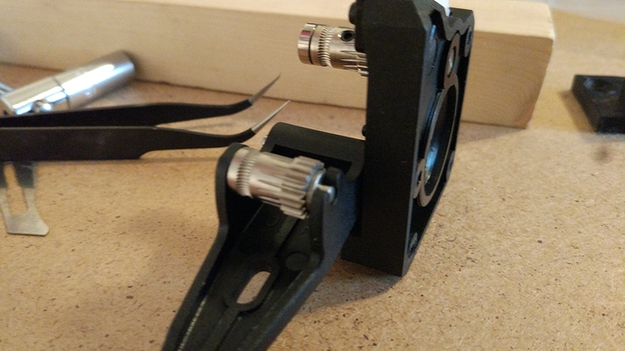
Ah one thing I notice for the bmg. One of the filament gear guide had quite some play and could slide back and forth for like 2 mm loosing the alignment with the front gear and filament. So I placed 2 C-clips to hold it in place.
That’s normal. Both BMGs I got from Trianglelab had that. When inserting the filament the second gear moves to it’s place by itself.
Just set it to 415 and leave it. It is worth it to check that it is correct by extruding a specific amount of filament. Mine was perfect.
Also you might want to install the anti backlash nuts flipped up, as now they actually would have a negative effect compared to normal nuts. The gantry is heavy, so at all times the nut is pushed down and it uses the bottom side of the threads. This is fine when using a normal nut, as it is always engaged with the same side of the threat on the leadscrew. In your case, the spring is actually pushing it up, so it might cause the nut that’s connected to the gantry to sometimes not touch the bottom of the thread causing inconsistent lines. If you flip it around, then the spring will push it down which will make it better. However you might not notice the effects in real use as the spring on these is pretty weak. This is pretty hard to explain, so let me know if I didn’t explain that clear enough.
I understood what you mean. I watched a YouTube video that had them installed in this way and was showing how it prevents the Z to drops lower than aspected. I will try and if I see some lines skipped on the Z I will correct it.
Thanks for all the info and the mount is pretty solid. I will post where the parts didn’t matched but basically is the V6 pocket once installed to the bmg that has to be shifted about 2mm towards the bltouch. To understand the direction.
Where did you get the anti backslash nut?
For the cables I highly suggest this:
Alex Tech 10ft - 1/2 inch Cord Protector Wire Loom Tubing Cable Sleeve Split Sleeving for USB Charger Cable Power Cord Audio Video Cable - Protect Cat from Chewing Cords - Black https://www.amazon.com/dp/B07FW3GTXB/ref=cm_sw_r_cp_api_i_O.lnDbZ2QPK1X
It’s semi rigid so cables will stay nicely curved in place.
[9,38€]5pcs Geekcreit® T8 Anti-Backlash Spring Loaded Nut For 8mm Acme Threaded Rod Lead Screws 3D Printer & Supplies from Electronics on banggood.com
https://banggood.app.link/Zfm0KoEMvY
Thanks for the cable sleeve.
I was looking configurating the firmware. I defined BLTOUCH. Do I also need to define the servo pin?
#define BLTOUCH
//#define BLTOUCH_V3
// Here is where you set your servo pin. EZOut Servo Pin Numbers: Ender3/5/CR-10 - 27, Ender 2 - 29. For 2560 boards look for the pin you connected the servo wire to and enter below.
//#define SERVO0_PIN 27

