You’re probably right because I didn’t bridge anything. It didn’t come with a wiring diagram. I was tempted to smash it with a hammer but I’ll save it and look into what it takes to bridge the pins.
Just another wrench in the works, those 2.54mm jst connectors are crap imho. Ive had them so loose they didn’t connect and had to recrimp them to get em to work again.
Im fairly sure if the factory sent you one pre pined for 18s it shouldn’t need to have the leads shorted. I checked the link you posted and it should have shown up correct. This is an older design but totally viable, if you get bored and want to try to fix it - I suspect they got you the correct cable harness but not the correctly setup bms if that cable connection was good at the header.
Glad it worked out in the end
Good news is it’s all working now and there was zero smoke. I’ll probably never dig into that thing and just stick with Daly in the future. Happy to mail it to you if you’re interested in trying to fix it.
Appreciate the offer but i have too many repairs on my list and don’t know what id do with it. ![]()
It’s been awhile since updating progress on this build but I’m getting close to wrapping it up. Bad news is I have to build a new battery due to crazy parasitic drain from the newer version of the Daly Smart BMS but at least P45B cells are still pretty cheap so timing could be worse.
This is what happened to the battery. I've never had this issue with the older versions of the smart Daly BMS
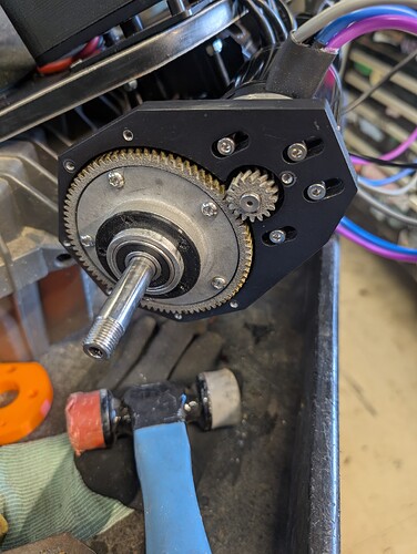
Decided to abandon the idea of going with straight cut gears in a Jump Drive and just start from scratch with a new herringbone drive system. Reduction is 5. The video below is the first prototype. It functions well enough but there are a few tweaks that will be made for the final version that reduce cost / weight and make adjusting backlash easier.
Parts for the V2 of this drive should be here in the next couple weeks. Things don’t always translate perfectly from 3d printing to actual production so a few changes were expected.
Calling these SirVesa's Beer Drives
The parts are just raw right now because prototype but planning to coat the second version in Steel It. If real off road testing goes well I’ll look into getting a powder coating setup. Will post some more details about the drive and each component once it’s dialed in 100%. Curious to see what you guys think of the design. It was obviously heavily influenced by Apex.
Looks pretty neat. Does it have a cover or you going to run it open?
Yeah it has a cover. Seals with a printable TPU gasket to make this as DIY friendly as possible or you can just use a V ring seal. Push fit adapters bolt on once the cover is installed.
So where does the deck sit in regards to the truck axles is it in line, below, or a little above? Anymore side shots in this regard?
How’s the camber of the board?
I’m super curious about doing a similar deck truck combo.
Herringbone gears, my beloved!
Are they SLS 3D printed? Or do my eyes deceive
Deck sits a little higher. Everything is apart right now in preparation or the V2 drives but I’ll definitely get some better pictures. Camber is in the stomp pads.
Yeah, SLM 316 stainless. Everything seems to mesh well. Can’t wait to put them through some abuse to see how they hold up.
I stayed up late last night building the replacement 18s 4p p45B pack. Shout out to @glyphiks for suggesting the JBD BMS and pointing me to the correct wiring diagram. I had always used Daly without issue but after their new model draining my pack to 10v it will be JBD moving forward. As a bonus, the JBD unit is about 1/3 of the price of the Daly and the app is a lot cleaner.
Didn’t get too many pictures because it was a “get it done” night but I’m confident in the build quality. Just waiting on some upgraded parts for the gear drive and an ESC enclosure baseplate from SKP then this thing is good to go!
Getting close to finishing this thing!
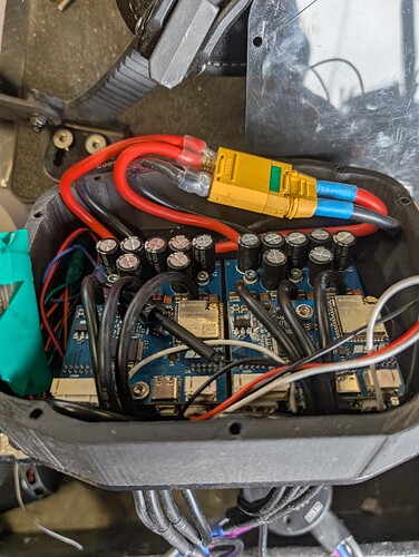
Solo V2 ESCs are in and programmed. Very happy that this version uses a momentary contact button. The OG Solos solution of having the button latched to turn the board off is a great idea, but after a dirty ride it gets a little gunked up when turning the board off and has to be cleaned regularly to prevent sticking.
The V2s didn’t come with a shroud or anything to protect the capacitors when trying to fit all of the wiring in the enclosure. It would have been easy enough to just make the XT90 connection outside of the case, but this board will definitely see some wet conditions and with an 18s battery I wanted everything inside.
It was easy enough to design and print a cover for the capacitors. The shroud doesn’t bolt to the case, it’s just holds itself in place when the lid is on. Now everything fits nicely and there’s no risk of wiring or the XT knocking a capacitor when riding in rough spots.
It took a couple variations but the drive is finally ready for some real testing. The herringbone gears seem to mesh well. Coating on the drive is a product called Steel It. It’s a mix of polyurethane and stainless steel with a cure time of 5 days. Definitely use a respirator with this stuff! It has great reviews and is supposed to hold up pretty well to abrasiion/ impacts. Easy to apply more if it gets scratched off in spots.
The drive is designed for EMTB trucks with wider hangers @22mm square profile like Airs or Dualities with no need to cut the motor shaft. I had a couple extra Apex push fit adapters so that’s what is on the board now but also designed some in CAD in case I ever need more. The gasket is 95a TPU and goes between the push fit adapter and the gear mount. Just a little grease between the gasket and the outside of the cover and there’s practically no resistance. Backlash is adjustable without opening the case.
Sounds like the baseplate is backordered for a couple weeks so it’s just a waiting game until this thing gets it’s first run!
This thing is finally done and ready for a test run tomorrow! The baseplate showed up today. Got it installed, along with a couple TPU gaskets for the ESC case.
I had to get a little creative with the wire management. Running the motor leads along the trucks and up into the bottom of the case resulted in the motor cans making contact with them during hard leans. This isn’t the prettiest but I don’t hate it and everything is out of harms way.
Very excited to see how these SLM herringbone drives perform tomorrow. The maiden voyage will be at Refugio road for a good mix of asphalt and dirt. It’s a steep climb with some pretty rough areas so if the drives hold up to this they should last through any of our other runs. If all goes well I’ll be posting pictures of this thing out on the trail! ![]()
If those drives work, count me in for a pair ![]()
Im on the EDGE of my seat, very excited to hear about how everything goes!
If they work I’ll post the files so anyone can improve or order as is.
Also super keen to see how these drives go for you!!
Can you devise a way to create some strain relief where the phases exit the can? I would be concerned about fatigue where the windings terminate to wires
The picture angle makes it look like the wire is routed tighter to the first tie wrap than it actually is. There’s a decent amount of slack there but still not a bad idea. Maybe something could be added to the motor spacer and printed with it.
Yeah the slack is good but it’s not pinned after it exits the motor. I might be paranoid but i like to get strain relief there. Incorporating with the motor spacer seems like a great idea


