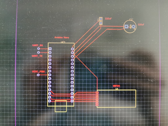
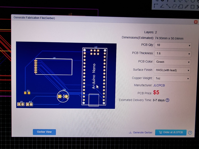
Can I send you the file I made so that you check it?
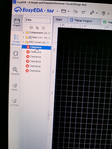
I made it in EeasyEDA
after selling my hummie build ([WTS][EU] Hummie complete - Bergs, Kahua, 12s6p 30Q, dual ESCape) I went out to test it last time before shipping. after 15 or so minutes, I got micro cut outs - they started to appear no matter what speed, but only after 10-15 mins or ridding.
motors are maytech 6880 sensored, 80A per motor, around 25 degrees celsius outside temperature
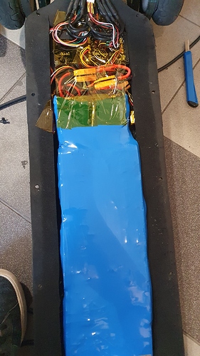
Removed enclosure, everything looks fine, isolated and in place. opened battery, every group was 3.61-3.64v, so not battery either. I am discharging through bestech d596, but everything seems fine with it. insides:
looked at my logs and here is what I see with motor temperatures:
so my guess is: vesc is thermal throttling because of too high motor temperatures.
first thing I will have to do is try riding unsensored. but how healthy is that for motors? they were hot when touching them, but nothing extreme, hot as always.
anyone with similar experience? what could cause those micro cut outs except too high motor temp?
My bad I’ll get it sooner or later
could this be related to the firmware issue reported in VESC-Tool 2.0 and Firmware 4.0 - The beginning of a new era - (SERIOUS) ?
As @sesat mentioned i had similar problems with thermal throtteling and more… Your motors are not too hot if you can touch them for 1-2 seconds. My motor temps jumped up and down (range of 40° C like in your log) but the root of the problem seems to be FW 4+, after downgrading to FW 3.65 my motor temp readings (and other RT data) were normal again and no more thermal throtteling. Strange thing is that I’ve used FW 4.2 for 1 month without problems and then they suddenly started. Give FW 3.65 a try I’m sure it will solve your issues.
does that program have a pcb layout editor, so you can draw out the traces yourself? i was never any good at starting out with a schematics editor and having an app generate/autoroute the layout for me
@sesat @rich thank you guys very much! Now when looking at your post, those motor temperature readings with such a crazy range are really not possible. And yes, motors are hot, but I can hold my hand on them as long as I want, they are not that hot.
I will try to downgrade and test again.
Yes it has!
Please save my life >~<
You can use any software, I just need a Gerber file for JLCPCB 
have you already prototyped your design on a breadboard, or are you adapting/deriving someone else’s schematic?
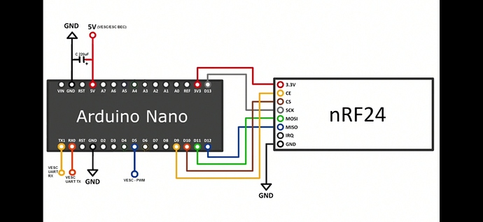
Its a schematic from a project already existing, only have an image of it:
Though is one is missing on tiny ceramic capacitor
Here’s the complete schematic made by myself:
The VESC and PPM Pins should be these pcb holes where you can solder in your cables
i’m not, they take up less space if the gas comes out, i don’t stagb the battery only the polymer bag it’s in
Looking for a little help on a alien power ev-t3 remote.
I get some weirdness when I try to test the failsafe.
If I shut the remote off after connecting to the board I get a humming/whining from the motors. When I reconnect the remote I get a few different outcomes.
1.) the motors spin as if the neutral remote position is now full throttle.
2.) pulling the remote trigger gives me stuttering and almost no power
3.) remote seems to function as normal.
There seems to be no rhyme or reason to which outcome I get.
Does anyone know if there’s a failsafe reconfiguration process on this remote?
Thanks
just curious what role does this decoupling cap play? sorry it’s not obvious to me
y u no just get a $3 nano and a 60cent nrf module, and use the 0.1" pitch holes to prototype your project and test your firmware before committing to a manufactured pcb?
Other people have done this successfully
The 22pF capacitor is to prevent a big where the Nano resets itself. The 220uF is for smoothing the 5V from the VESC.
Btw I made it work.
For me its simpler to prepare everything as a schematic, then use autoroute.
I’m missing the GND connections somehow though…
great job getting your routing done
i thought the cap goes between rst and dtr (or rts) not gnd, but see those are the kind of mistakes i make that lead me to prefer prototyping on the breakout before getting pcb’s made
Just solder a wire on there and cut it with snips when you’re done.
How big is a nano remote?
Like approximate length and width?
