What is the best cell to use for an external battery to power lights.
I was thinking 5s2p (110 watt hours/6 amp hours)
All depends on how many watts the lights draw and how often you want to charge them and how much space you have.
Figure out light draw take time you want and multiply say 20W lights for 10hrs of runtime per charge is 200Wh if they draw less or your cool with less time can go lower
Will have like 10-20% loss from voltage conversion with buck or boost converter but ideally source voltage is close to target voltage.
1 Like
that was not my question 
I will choose lights accordingly and if need be i will increase the power of the pack.
@b264 uses LiFePO4 cells for smaller boards and i know there are better cells than 30q for smaller packs but don’t remember which ones
2 Likes
oh heh I see yah well thing is the draw on the lights is generally going to be much lower than the draw from the motors, so say you have 16W lights and you are giving them 8V supply then you are only drawing 2A from the cells so you can go with lower discharge rate higher capacity cells for the lights.
1 Like
I am looking at some 52W 12V lights LoLz
So i need a biggish pack
The best cell for an external non high amp draw flashlight would probably be the samsung 50E, but its not an 18650, its a 21700.
The best 18650… Its a tossup imo. However we all know the common good cells: 30q, VTC6, VTC5a, etc.
In my eyes 21700 cells are more well rounded, as in there are fewer tradeoffs. The samsung 30t is a great example, 3000mah and 30a/40a limit, very good IR… you see what I mean
3 Likes
One of my solder pads going to bat- from my VESC lifted off of the PCB and shorted with the E-switch ground, luckily those fets were already fried (lmfao) but does anyone think its worth trying to fix or should i replace the whole VESC?
1 Like
52W light divide by 12V they are going to be drawing about 4.3A (at that voltage) so anything with a continuous discharge above 5A should be good in 1P configuration (if you did 3S with buck converter), not familiar enough with all the current options but would go from there look for the highest capacity cells that will supply that continuous current (at bare minimum), if going lower voltage on the batteries than 12V you’ll need to account for that (try to work out everything in terms of Watts is generally the way to go, watts out is watts in minus some losses or power used in any given component)
https://www.18650batterystore.com/Best-18650-Battery-Guide-s/142.htm
https://www.18650batterystore.com/Sanyo-18650-p/ncr18650ga-protected-pcb.htm <-- only has 10A limit but is suggested for “flashlights” and has 3500mAh if going 3S maybe worth considering
1 Like
When you say ‘those fets’ do you mean the VESC, or the eswitch?
Photos of it? It sounds kinda gnarly
1 Like
E switch FETs fried open but it’s looking like the bat- may have contacted bat+ looking closer at it. Ignore the lump of solder on the negative pad I don’t have a strong enough soldering gun to remove it.


Edit yeah I forgot the photos,
1 Like
There is no photo, if you tried to add one
e: now there is
if you could get the wire off the pulled pad there are other places you can connect the GND but yah depends on how much the time/effort is worth rather than binning it, might be worth salvaging to keep running for a bit though since I keep hearing murmors of the torqueboard vesc6 being close
1 Like
No I meant the bat- solder pad lifted off and touched the e switch ground, mad sparks and whatnot but idk if the VESC is fried.
can you add multiple lights to the pack? how does that work?
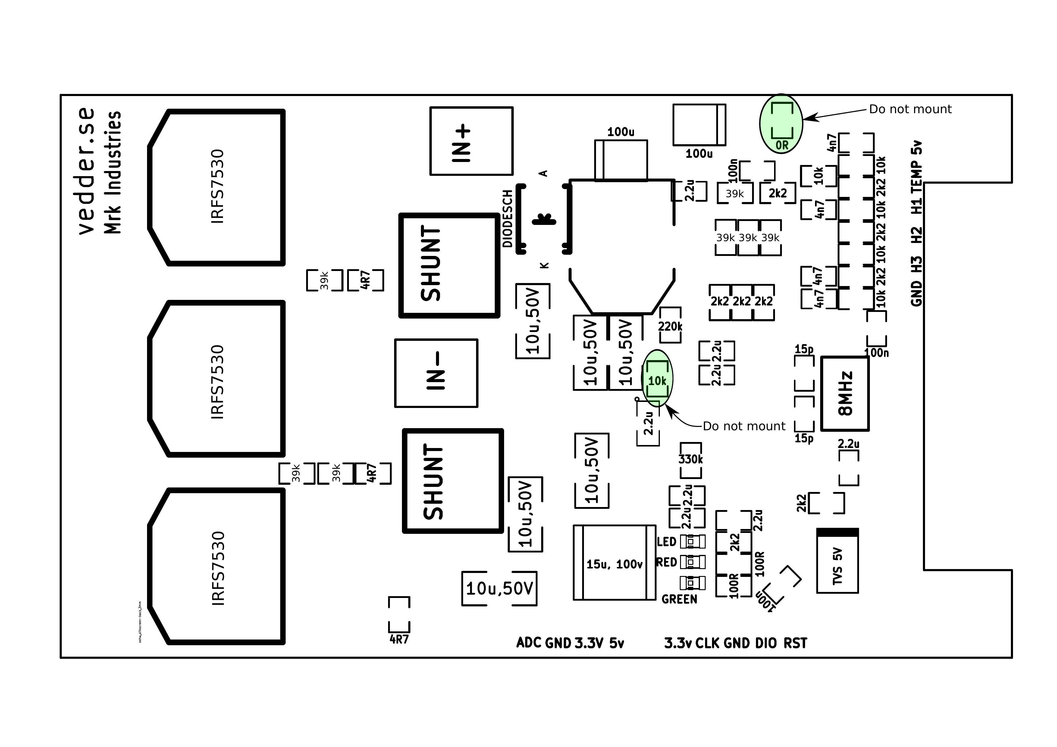
ah okay I was thinking of the older VESC 4.x design but still maybe the shunts are there for the mosfets I’m 99% sure are connected to GND was thinking could just tack onto the back of one of those maybe but dunno the newer boards that well
Yah sure each connection in parallel coming off of the battery is getting the same voltage they’re just all drawing current from the same battery so if one light draws 5A two lights will draw 10A, more overhead the cells have in terms of max continuous discharge the less their voltage will dip when under load so I would add some margin in terms of discharge you need vs discharge they advertise… hope I was answering the right question 
1 Like
I apologize im not super familiar with diagrams like this, meaning the shunts may have taken the brunt of the short? I pray theyre not SMD.
LOL
I struggle so much in physics and maths ![]()
![]()
oh no sorry I was just looking for a place where you can re-attach the GND if the pad itself came off (it’s hard to tell from the pictures really), the shunts and GND were all connected on the older design of the boards but I haven’t had one of the ones you have there on hand to look at, which particular VESC is it? sorry if I missed this
Yah all good I was pretty okay at that stuff in High School but I’m like 20 years removed from that so had to go back to Khan Academy for some brush up and few really good ones on Youtube too on this channel (kinda dry but you learn)
2 Likes