Hmmmm I hadn’t thought of that, faak me… I have copper shielding foil that we sometimes use on noisy quads… one of my boards is about to get a refirb. I’ll wait and see what @Deodand has to say about the matter, and maybe wrap, and twist the sensor wire around the phase wires…
where do i find a “ground” on an electric skateboard?
2 Likes
ESC ground
battery ground?
the gnd pin in the sensor harness? (i assume this is tied to the mcu gnd pin)
1 Like
Quick lunch burn on Beta7, no issues to report @Deodand.
3 Likes
Yes, either that or the ground pin in the servo header or the ground pin in the SWD header or the ground pin in the CANBUS header. Definitely NOT battery negative and NOT the big fat black wire powering the ESC.
1 Like
Im on 5.4 now for metr,
the april 22 version of fw5 and still no luck…
My remote however, does work. @ducktaperules thanks for the tip
1 Like
For some reason my motor temp shows as -99.9C
I’ll look into this.
1 Like
you got some kool motors!
3 Likes
@Deodand What is the word on motor detection with belts and drivetrain attached? Do you think it matters? I’ve heard both ways over the years.
I just did an experiment and it’s not really changing the numbers much at all, having the belt and wheel connected. However, changing the firmware version changes the numbers a significant amount.
these are consistent with or without drive train connected
TB6380_3 new values detected at commits a8ccdba / 12a7106
I: 22.51A
R: 14.0mΩ
L: 6.01μH
λ: 4.335mWb
these were the average of several detections, all with no drivetrain connected
TB6380_3 old values detected with firmware 4.2
I: 23.37A
R: 12.20mΩ
L: 8.98μH
λ: 5.013mWb
Both of these were the same physical motor, ESC, and wiring. The enclosure hasn’t even been opened.
The drivetrain didn’t seem to affect the numbers at all on the experimental version but I hadn’t tried that test before.
5 Likes
I would recommend double checking them with an RCL meter, if you have one on hand.
One possibility is that during the inductance measurement, the inertia of the drive train keeps the motor locked at a different rotor position that has a different corresponding inductance.
The best practice would be to do detection without the drivetrain attached because potential inbalances in the drivetrain can cause the motor to move during detection and skew the values by the generated bemf.
Our motors probably aren’t too similar, but for what it’s worth, the TB6380 I have, measures a phase resistance of 21miliohms (power stage included, it is about 37.5miliohms line to line from the bullets), phase inductance of 15-17uH at 30khz (19uH at 1khz and low current). And flux linkage of .00475Wb. These are measurements taken using an RCL meter and a separate power stage.
4 Likes
Unfortunately, I don’t have an RCL meter here. To use one, I’d have to skate across town.
What does firmware 4.2 detection say?
What does firmware 5.xxxx detection say?
2 Likes
4.2 firmware on trampa vesc mk3 said something like 24miliohms resistance, 9uH inductance, .004901 Wb flux linkage.
3 Likes
A post was merged into an existing topic: Welcome to Derail Jail
You need to quit answering questions with big words pretending to be an expert on things where you lack complete understanding. If you want to participate in the discussion try asking questions about things you aren’t sure of instead of pretending to know everything when you do not.
The number one thing I learned after 6 years pursuing my PhD in robotics is that there are piles and piles of things I lack a complete understanding of. You could really do with some of this experience I think.
The method we now use (as of 4.xx) to measure inductance is almost entirely independent of inertia or current motor position discounting imperfections in the magnets/stator. The excitation is rotated through 360 degrees electrically, as such the majority of influence of motor positioning is removed.
When you measure with an RCL meter it is neglecting the on resistance of the power stage and the PCB. This is part of the system you are controlling and so that resistance should be included in the measurement. It will be around 2 mohm putting the resistance measurement basically dead on.
@b264 As long as the motor still spins up succesfully with belts on then the latest routine’s are more robust than ever to external loading. So if the flux linkage measurement passes it should be all good.
The measurements from calibration have been changing some in recent updates because Vedder has built out a motor simulation in which he uses the same control algorithms on a simulated motor. With ground truth data from a simulated motor it has been possible to find errors in some of the existing routines algebra/scalings (few missing 2/3rds here and there mostly) and refine them. At the end of the day this is what truly matters, having calibrated numbers that are scaled correctly to how they are used in the controller. Really excited about the progress Vedder has been making.
22 Likes
Just curious, does these new improvements you guys have been doing will improve performance at low ERPM / duty cycle? If @Gamer43 is right or not I don’t have the experience to tell, but that at low motor speeds the torque is lower than at higher speeds is a fact, not a big deal breaker for sure, and most noticeable on direct drives / hubs
Will install the new FW on my small board where this is really noticeable
1 Like
Yeah I did some testing with this and have noticed it on some setups, though I’m not completely sure if its just perceived acceleration. When I’m already moving at 10 mph the same acceleration might feel more intense? Not sure. I should really just go to a flat ground place and look at acceleration of ERPM vs constant motor amps.
There was a big update to hall sensor interpolation which produced smoother sensored control, this should improve low-end torque slightly also. I’d also really like to do some tests on ground truth measurements of amps drawn. I’m wondering if maybe its simply a matter of over/under estimating amps at different ERPM because I’m pretty sure the position tracking is solid.
8 Likes
I think need to make a hotkey for this response, i would use it all the time.
If only you had some sort of device that could measure the acceleration built into the stormcore . . . ![]()
5 Likes
I merely said it was a possibility, thank you for indicating to us that this is not the case ![]() .
.
Is this the 360° excitation you are referring too?
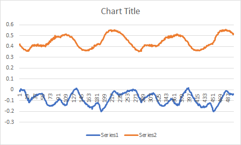
My 15-19uH measurement corresponds to about sample number 19, meaning it is the lowest inductance. Orange line corresponds to proportional inductance as a function of rotor position. This does not explain why the number measured by the VESC is so low. From my understanding, you need a baseline measurement for this strategy. Every application note I read says to determine this value using the first and second time constants of the step response by driving phase A positive, phase B ground, phase C floating, unless there’s some formula I am missing and the stator inductance information is right in front of me and I am just not seeing it.
If you paid attention to my post, I said the motor’s line to line (from the bullets) resistance was 37.5 miliohms, which is a phase resistance of 18.75miliohms. The 21 miliohms was the resistance I measured using my own power stage. In your words, the measurement from my power stage appears to be “dead on”, and the VESC is off by an additional 3 miliohms per phase.
Now why is this important? Looking at the equations in the observer, deviations in the estimated resistance and inductance, multiplied by current, will appear in the flux linkage estimation. This in effect introduces cross-talk between the current waveform and the estimated BEMF waveform, resulting in a phase shift of the estimated flux linkages proportional to the ratio of current, the R & L deviations, and the actual BEMF. This phase shift alters the angle between the rotor and the magnetic field so that it is no longer 90° and in effect reduces the torque generation efficiency as the cross product is no longer 1. At low currents or high BEMF, this shift is small, but at high currents and low BEMF, this phase shift becomes significant.
Here is a video demonstrating the performance of the observer during and after repeated stalls, using the values that I measured. It appears to be able to restart from stall condition, there is full torque generation down to about 1 mechanical RPM (although this is not clear in the video). There is no open loop or sensored intermediate, it directly polls the flux linkages from the observer. There is a 100% pulsed d axis current injection at 60hz and 50% duty cycle when the ERPM is below 1000.
It also accomplishes this at 30A. Going to dyno test this in the next week or two.
Also worth mentioning that if I use the values that the VESC detects, the observer utterly fails to track until a rather high open loop speed.
Feel free to completely dismiss this. I am just trying to provide helpful information.

2 Likes
yes please!
g-meter data for end-users, please
1 Like