Intro
I ride downhill mountain bike and National Forest OHV trails. I like carving, bonks, and drops so self-balanced boards are good because of the snowboard-like feel, maneuverability, and small footprint. When I converted this board from an FM ESC to VESC, the focus was to minimize weight, improve weight distribution, and improve repairability.
Parts List
- Little Focer v3.1
- TFL Growler WTF Rails
- Feiben 10x6-6 treaded tire
- FM hypercore motor (standard onewheel XR motor)
- Chi battery CBSP 15S1P
- Ignite 1” lift kit
- 3D printed battery enclosure
- 3D printed esc enclosure
- TFL Bang Bumpers
- DIY esc heat sink
- 3D printed rear footpad on 0.09” aluminum plate
- 3D printed front footpad with activation switches on 0.09” aluminum plate
- XT-90S loop switch
- External LLT BMS 4S-21S
- Littelfuse 80VDC fuses
- Hoyt puck/receiver
- Rear binding, formed 3/8” aluminum rod, foam, baseball bat grip tape
- Front binding, 2” straps, Velcro, 3D printed release

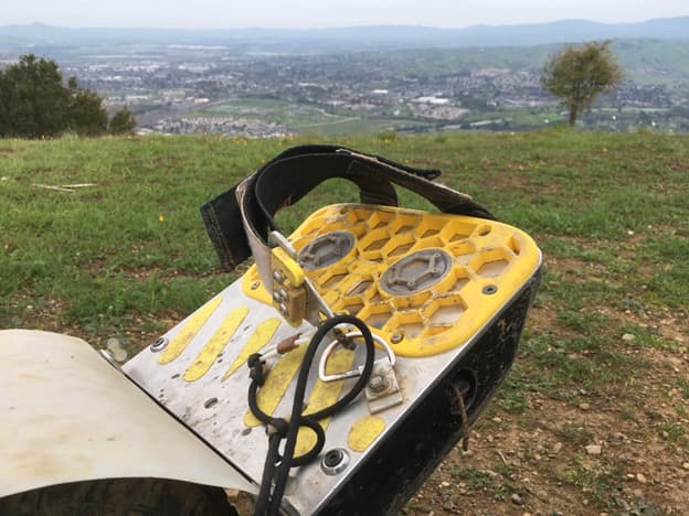
Glamor shot

Electrical Diagram
ESC Enclosure

The wiring harnesses that go in the ESC enclosure. The fuse holder connectors to the battery were changed to 4mm bullet because I could not get two XT60’s through the ESC enclosure penetration. I did not take a picture of this though.

I changed my molex connector after seeing how Mario from board garage did his.

XT-90S loop switch I made. Drilled a small hole in the plastic for the string. Potted with epoxy and heat shrinked. This is mainly used to anti-spark but also good in emergencies or for storage.

Typically onewheels have the charge port on the right side of the nose but I plan to charge a different way so we can use this spot for the loop switch.

All the wiring is installed in the enclosure.

The main wiring harness to the batteries is installed.

Little focer 3.1 installed on custom heat sink. 1mm heat pad.

ESC and heat sink installed and wired up. 0.07” o-ring seals against the heat sink for waterproofing. I also installed a Hoyt puck receiver, not shown.

All closed up with motor, front foot pad, and battery hooked up. Just have to install the front foot pad over it. One of the advantages to this design is that the aluminum plate of the front footpad is in contact with the heat sink for better cooling.
Battery Enclosure

The battery enclosure is designed to fit the Chi CBSP. The orientation of the wires on the battery required some extensions for the balance and mains to exit the top port of the battery box.

Battery and wiring tucked in nicely. 0.07” o-ring installed. This has proved to be very successful in keeping out water and mud.

Because battery protection is so important and I’m dropping on rocks and stuff, I made an aluminum shield for the bottom of the battery enclosure. The bends improve the stiffness. There is also a bumper under this plate but I did not want to rely on that alone.

Shield installed

All closed up with balance connectors and mains. I pot the base of the JST connectors with epoxy and add some tape for some extra protection around the balance wires.

Installed on the rails

The top port of the battery box penetrates into this smaller connector box. The interface is sealed with a tangential o-ring. I later changed the set up in this picture to give me some more slack on the connectors.

Four thumb screws, aluminum plate, and o-ring keep the connector box sealed.
Charging
I wanted to do an external BMS to keep things as simple as possible. I chose LLT because they are cheap and there is a good amount of experience in the community. I went with the 4S-21S unit because I will likely upgrade to 20S in the future.

15S wiring diagram

20S wiring diagram

Balance connectors


Final assembly with 3D printed enclosure

Charging. Drok AC-DC for power supply and DC-DC for voltage regulation.
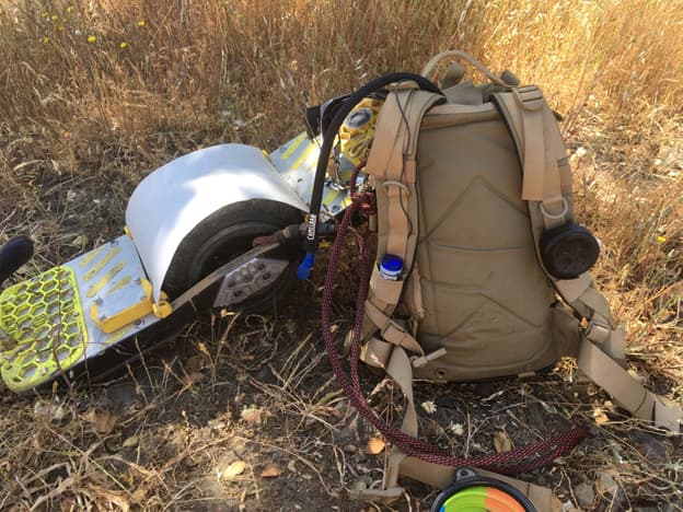
Extra Pics


What’s next?
Eventually I will build some 20S batteries to replace the 15S. I’ve been working on VESC code to improve trail riding. I will probably release a package in the near future so anyone can use it.