I don’t know since every action requires and equal an opposite reaction. If the wheel accelerates in one direction, a force must be applied to something in the opposite direction. In the case I’ve described the rotor is pushing against the stator via magnetic forces, the stator is attached to the axle or truck.
The stator axle shouldn’t be connected to the axle anyways. It should be rolling on bearings if you’re connecting it to an axle. That should be pretty obvious.
Not sure why you are beating the 8mm axle issue as that’s not even an issue anymore since it’s been upgraded.
Seems like you’re beating up on old news.There was only one prototype of that available so why so much issue on an 8mm axle that doesn’t even exist.
I’d imagine some of that force is taken up by the bearing before the axle.
^these reasons from the OP
I’m not sure why you think this, the magnetic forces travel at the speed of light from the stator to the rotor. If you took the motor off the axle, held the rotor (tire) in your hand and applied some motor current, the armature/stator will spin and effectively become the new rotor until you twist up the wires. Locking the stator in a particular orientation relative to the ground via the truck and/or axle is what causes the wheel/tire to spin, instead of the armature/“stator.”
Probably because the guy that does this for a living said.
So if it doesn’t apply any torque to the truck or axle, what does it apply it to then?
No one said it applied 0 torque they’re just saying it doesn’t apply 100% of the torque you’re suggesting
i am staring at my carvons right now. isnt the rotational force applied to the hanger?
i’m glad you brought up the hanger. hangers are typically made of aluminum. steel has what’s called an “endurance limit” - aluminum does not.

basically the charts shows with enough stress cycles, aluminum can fail with very little stress per cycle, in contrast to the material called steel.
and how is that any different in a geared drive with mounts?
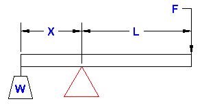
the length of the “lever” is often different (shorter) with direct drives, which can multiply the force.
i thought shorter levers would apply less force? I remember the reading david and goliath story
i mean the the part of the lever on the opposite side of the fulcrum from which the force is applied.
^labelled “X” in this image
doesnt make sense. if it needs to move 100 kilos of mass, all other things being equal, its gonna apply the same amount of force whether its a motor mount or a direct drive connected directly to the hanger.
I thought the only reason we went with 10mm+ axles on Direct drives was because of the extra length needed on the trucks.
the same amount of force can be generated at the edge of the wheel while different amounts of stresses and forces are developed at different parts of the drivetrain depending on the leverage at that point.
if you have a force at the wheel the same amount of force is applied to the hanger,somewhere. It’s the same force applied to hanger regardless and adding a gearing isn’t decreasing it.
^earlier I described the force on an axle during a failure. let’s look at the force applied to the road surface at the edge of the wheel (the pounds thrust) happening simultaneously:
total force at wheel edge (motor thrust, 84mm tire diameter): 363.57 newtons = 15.27nm / 0.042 meters wheel radius
total force at wheel edge (pounds force, 84mm tire diameter): 81.4lbs force = 363.57n * 0.224 pound force per newton
total force at wheel edge (pounds force thrust, 84mm tire diameter): 81.4lbs force = 363.57n * 0.224 pound force per newton
total force at axle (pounds force): 855lbs force = 3817.5n * 0.224 pound force per newton
^comparison between force at 2 different points in the drivetrain, the axle and the wheel edge, based on the leverage at that point.


