Myself and others have run into needing them for brake signals for things like ebikes. This creates more or less a binary input for the ADC channel (brake or not brake). Having a pull up or pull down creates a strong and well defined threshold for this sort of thing and helps reject noise.
 I’m not an expert so sorry in advance if im wrong, but im not gonna write “i think” or “maybe” before every sentence.
For the stm and CPUs in general when a pin is configured as digital IO it has either a pull up or pull down set internally in the CPU so it will either be low or high and you can toggle it by shorting high/low (0ohm). But when you tell a CPU to use an input pin as analog, it actually sets it to “floating” where its 1.5ish volts and it is very temperamental. But this is because the CPU doesn’t know your application and therefore can’t know if it should be high or low without any signal.
When you wire up say a pull down, i could say the buzzword voltage divider, but whats happening is that all the pixies have a path to ground and therefore don’t go to your analog pin, then when your pot or input signal gets to be a lower resistance than your path to ground, it starts siphoning some pixies to the high pad that it is connected to. (its not actually lower, if the resistences are equal itll be 50/50 each way, if its lower itll be more than half) The ohm value of your pulldown will affect the operating range of your input as well, if you have a 1k pulldown and you input pot is 100k-50k (will allways be low) you wont get much signal, and the same is true if your pulldown is 100k and your signal is 1k-2k (will always be high). This is why CPUs require you to supply a pulldown or pullup when a pin is set to analog mode.
So anyways thats why the balance app needs a pulldown for foot sensors, i tried to code it so that it wouldn’t, but thats just how CPUs do things.
P.S. I hope this is all right, im half bluffing, im a software guy not a circuit guy,
In the case of arduino’s, they have digital pins and analog pins. The digital pins don’t automatically have pull-ups or pull-downs, but you can configure them to have a pull-up. I don’t think the option is there to do this with analog pins.
Ardunio analog pins can be used as digital pins with the pu/pd resistors.
So is that effectively the same thing Shaman is describing here? It seems he’s effectively using analog pins as digital inputs by using pull-ups or pull-downs - right?
I took it as you can scale the range of your input using a PU/PD as voltage divider on an ADC. and that you could scale that range to be very binary, like digital I/O. but for other reasons you may need to scale it but still non binary. [ 0 expertise here. so I could be wrong. ]
This is correct. Typically you’re scaling for a throttle or brake so you want a decent range.
Sooo, what will be the length of the Cheap FOCer 2 without the capacitors?
100mm. Same as the recommended heatsink.
And what about without capacitors and heatsink? In the original post you wrote 100mm without enclosure/heat sink.
Yeah i need to update the length to reflect the horizontal capacitors. Should be 60mm x 120mm x 14mm
All spoken for right now with friends, but I’ll let you know if that changes.
Looking to source one of these with an IMU (I have the soldering skills of an ape and an iron with no direct temp reading), if anyone in the US has any they would be willing to sell please message me.
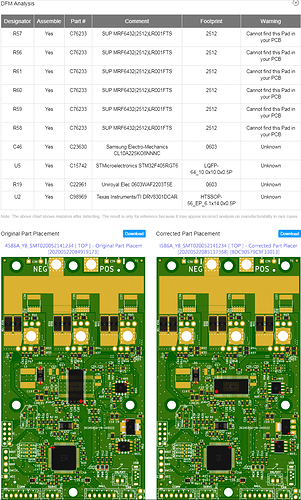
Ordered 10, they just went through DFM and the rotation for various parts was corrected as stated in the github  .
.
I just finished installing IMU’s on 5 boards using a hot-air station. I apologize if this has been covered before, but I’m wondering if there’s any test I can do to make sure I have all pads soldered and no bridges. Either test points on the board or maybe a functional test?
Thanks for any tips.
The only thing I do to verify the IMU is verify it’s functionality in the VESC Tool. I just enable the IMU in the VESC Tool and shake the sh*t out the FOCer. If I see feedback, then I did it right.
I’ve soldered some quite poorly such that they don’t work, or even so bad that the vesc won’t boot, i was able to redo them and everything seems to be fine and undamaged. That’s not really conclusive evidence of anything, but i don’t think you need to stress.
Thanks guys. Using the VESC tool makes complete sense. I don’t know why it hadn’t occurred to me. I thought maybe there was a test app, or I’d have to write one.
In other news… I’m super impressed with the documentation you guys put together. Well done!
Power from the battery is what I recommend here. This will test things a little more comprehensively like the DRV’s ability generate 5V.
