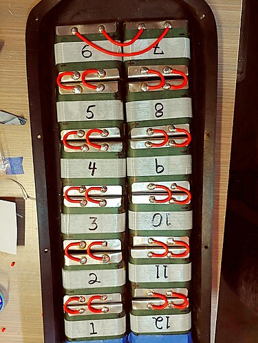
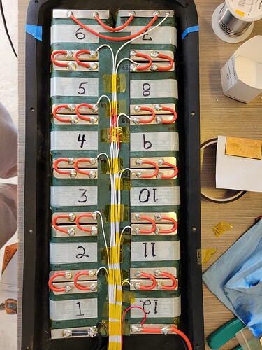
What is your plan for your parallel connections? What material have you sourced so far? If you’re making series connections w silicone wire there will likely be no need for you to stack nickel but it depends. Present techniques favour making your p connections with 30 or 40mm x 0.2mm nickel.
Stacking nickel is a pretty bad idea as those welds will be far weaker and have the potential to break. Avoid stacking.
stacking benjamins
Damn, I guess I’m a bit too late on that, I’m using 0.15mm*8mm nickel strips, I’ve read they can carry around 15Amps continuously safely. At this point I’ve done like 10 P groups first layer out of the 12.
Thicker nickel wouldnt work since I don’t have a strong enough welder. I’ve asked around and there is only one firm in my country who was willing to do it but they asked more than the material cost of the full battery so I opted out.
At this point idk which direction to go
Also buying new stuff(better welder etc) is out of the question bc I’m a broke college student
Check the top of this post, I posted the link for the nickel I use.
What if I can’t choose any other options? Is there a way to make it safer in any way?
You’re much better off with this stuff than what you link in the first post for a high amp pack.
If time is not an issue, you can also source the nickel from Aliexpress for less money.
https://forum.esk8.news/t/sourcing-nickel-strip-sro/3228/68
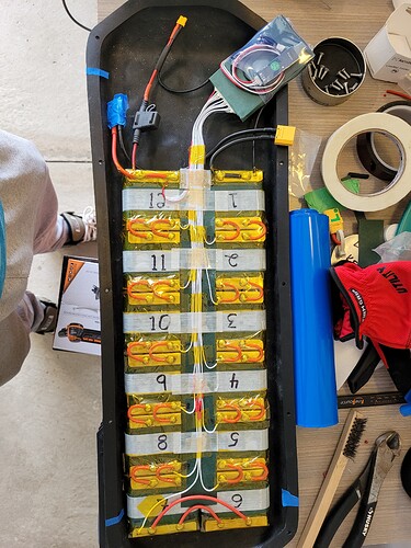
Just FYI, I’ve constructed the exact same pack using the nickel I’ve linked above, 14awg x 2 for series connections and 12awg for the main terminals. Your pack will only be capable of 120 amps continuous and you’ll really never pull that much current anyway. In esk8, the current draw is not consistent like that. We have spikes of high current for a few seconds which are easily handled by those wire gauges.
its a bit too late for that, ive already welded it and i dont want to tear it off possibly damaging the pack in the process. your pack looks neat tho. also i have a different configuration for the cells since the size of the deck determines the size of the custom enclosure and i couldn’t fit the cells like you did.
Well, I’d suggest posting some pics of what you’ve done so far on the battery builder’s thread and get some opinions on how to go about it. If you bought the “ladder” style nickel, it will still likely be fine in a bus bar orientation but if you have space constraints it’ll be helpful to see some pics so we know what you’re working with.
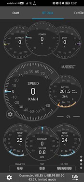
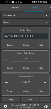
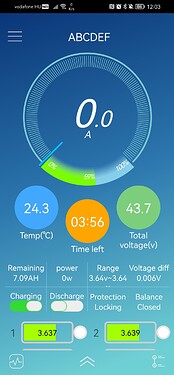
I’ve been making the finishing touches on the board and one thing catched my eye, the VESCs battery level readings are different,strangely the remote shows the correct value.
what did i miss?
12s
So, the range in the VESC tool is way off but the % of battery left is pretty accurate. Not so much on the remote. At nominal SOC (3.7V), you have roughly 30% of your battery left.
What version of the firmware are you using?
At first I thought the vesc was the problematic element…
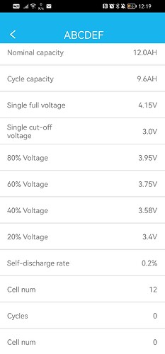
i don’t really care about the remote. But rather the bms, I have these options, but I don’t really know specificly at which voltage how much capacity the cell has remaining.
The remote acted like this from the day I bought it, flipsky, so like what did I expect? Haha
No big deal, pretty sure there is no fix for it, since Ive used it with 3 VESCs with the same results…
Hey is there any reason not to use XT90 anti spark on all my batt connection instead of regular XT90?
Nope


