I was on the 22/3 FW
Connected the VESC Tool android app of 10/4 using BLE
And then I flash FW by [Upload All] button using BLE
Flash completed via BLE
Reboot VESC
Try to connect using BLE but app started not recognising VESC with error screen below.
Why can’t I set ‘Absolute Maximum Current’ to 130A? 400A seems to be the minimum.
When I checked the fw version of the vesc over CAN it stated that it was on beta 3 but this wasn’t the case. Is it possible that the version check only is valid for the main vesc?
I was able to recreate DVR error and it was because of first going in reverse and then very briefly accelerated forward but without load, so very aggressive change of direction.
It is set to 400 intentionally to disable abs over current faults (that is the only thing that setting is used for, throwing faults). They are redundant with the DRV and were giving false positive with the unity hardware previously so we decided to disable it.
Is this while you were riding the board? Did you re-run motor calibration? Can you share the detected parameters?
The unity has only one micro controller so it is impossible for it to be on different FW versions FYI. It may be the way metr is showing the version or something is off? Or was this from the tool? Screenshots would be helpful.
No, on the bench, so just the wheels spinning. Yes, redid motor calibration, here are parameters:
Yeah, I thought the same thing but when I wanted to do remote PPM calibration the system told me that one of the vesc’s had older firmware and I needed to update. (PS: at that time I hadn’t done motor calibration yet and just restored configuration for the ‘old’ calibration values.)
Maybe I’ts possible to recreate this by going back and updating again.
It was from the tool but since you are saying that there is only one microcontroller that is maybe normal
Took this firmware out for a short ride today on the neobox V6, dual via canbus on TBDDs. I am glad that temperature sensing still works with HFI and sensor cables plugged in.
Set up HFI (20/14/14) and all is well when riding for the most part- so smooth compared to sensors somehow… After my ride today I noticed on the bench that with no load the motors just spin back and forth, like 180° one way then reverse 180° then forward 180° and so on… I don’t know if this is normal, this started happening after changing around my HFI settings but it’s still doing it after reverting the voltages. When riding I noticed one motor would reverse for a second and then keep going. I’ll keep fiddling around… I’ve probably watched @Deodand’s tutorial like 8 times now, lots of info in there to take in. Is there a real benefit to setting a lower run voltage than max voltage?
Overall it was all stable minus a couple minor hiccups with HFI, I didn’t push too many amps in HFI though, and when I did I noticed they would cog a bit.
Does anyone have any experience with the temperature compensation setting and how much effect it has? It’s off by default, but I think it might be useful since my motors tend to get 60°C hotter than the temp they are detected at… Also does anyone have any experience with Stator Saturation Compensation setting? I haven’t tested high motor amps on this FW yet, but 90-120 motor amps would cause cogging progressively worse the higher the motor amps… would this setting possibly allow higher motor amps without cogging?
Sorry for the noob questions… I’d rather ask than break a bone testing every random setting if anyone else has experience with these settings.
In my experience temperature compensation can be beneficial for some motors, I often find when using it that turning down the detected resistance 5-10% before enabling it seems to make it work smoother. If you are experiencing some cogging etc as the ride progresses this might be useful.
I wouldn’t use this, I haven’t found a motor at the skateboard scale where it helps yet.
The main benefit is less heat in the motors when HFI runs, it wastes some power, especially at higher voltages. Using detect_inducatnace from the terminal will let you know how many amps are pushed for a given voltage (duty*batt voltage).
This is indicative that the start voltage sequence isn’t achieving the desired result, you will want to play with start voltage to dial that in properly.
Check your observer gain at minimum duty, if it is non default value that may be causing the 180 back and forth.
Also yes, HFI is better at tracking the motor than hall sensors. I’m hoping the new hall_analyze command is a first stab at assessing the problem with hall sensors.
im having have some weird things happening with my hall sensors, startup is smooth if im flat or leaning toe side but it stutters if im leaning heel side. Im assuming its a hardware issue not a software one but it is odd.
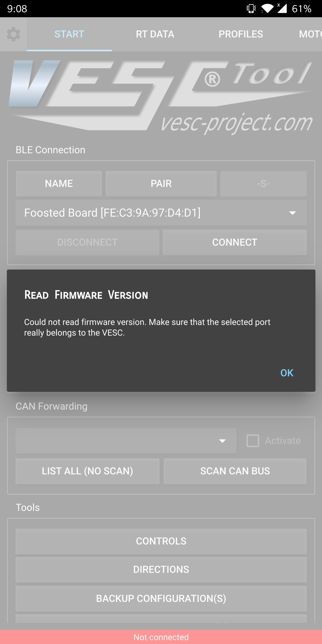
so I finally hooked up an nrf module to my ESCapes running fw5, beta3 currently. I have the matching test version Android app installed and I’m getting the firmware read error, am I missing something?
nrf51 module flashed with vesctool, uart @115200
That sounds more software related; under more torque needed, strange behavior…Like one motor could not match the amp with the other to work properly together and it sutters…My thoughs…
I’ve also gotten nothing besides firmware read error (connects for half a second then disconnect then show the error) – on any ESC and on any HM-10 or nrf module.
This was on various firmwares 4 and 5 of any version I tried, with Rx/Tx swapped or not swapped
I said “fuck it, don’t need that” and shitcanned it all. USB for the win