Post it to YouTube then post a link here, it will be embedded in the message.
2 Likes
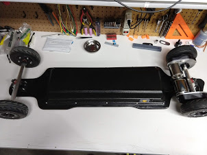
Here it is
Sound like hell but at this time the top plates havent been added and no grease was added too

7 Likes
really nice
yeah go for alu for the mount or extend the motor shaft as i did to print thicker
tht was the reason i went for this long trampa trucks they just offer enough space
KR
Interesting - I am curious how much more torque you’re applying in your build than I am. The shaft on the torque boards motor is 33.5mm long. The mounts I use are 14.5mm thick which leaves 19mm (sans mounting space)… closer to 18mm of actual interface length with the Drive pulley. This pulley also does extend beyond that threshold by 6mm. The mount has had no issues holding up and my only failure mode was due to loose mounting screws causing the pulley and motor mount to interface while riding - heat up and fuse together.
Edit: not using gear drive but the torque applied to the motor mount shouldnt differ that much at the mounting point between gear and belt drive. Then again I dont know.
Edit again: Mounts are 3d printed (PETG 40% Infil first version) Trying out PLA 40% for giggles, I also set a chamfer on my shaft-hole to allow for a “closer” interface while not sacrificing the strength at the motor mount holes. Ill toss a picture up here if desired.
That said, @Sharky I am super interested in your work here and look forward to more details from you once testing is complete.
1 Like
The shaft i use is 10mm thick 38mm long
For the motor pulley im using a metal one
The wheel gear is made out of polymide 80 infill and the mounts ate out of carbon nylon cf15
So far im really upset no wobble nothing breaks im running dual 200kv 3200w 6374s motors on a 12s5p setup 70a motor current
Torque uphill is really nice even with the 107mm flywheels
1 Like
how did it do?
1 Like
I’ve been meaning to post an update here forever and have been dragging my feet, so here goes a years worth of catch up:
Last I posted I was doing some torture testing on the gears to see what it would take them to fail. From there I tried to put some miles on the gears to see how they would hold up. from this testing I learned a few critical items to making 3D printed gears work:
-
Lubrication - At first I was using some lame-o grease that wasn’t up to the job, I changed to Aeroshell 22 and it has worked out very well.
-
Backlash - I finally figured out that every set of gears I failed (3 I think) after the first set i failed (bad lubrication) was due to improper backlash .The 3D printed teeth are both intolerant to backlash that is set too close (causes the gears to fail after a few miles), and a little trickier to get the backlash set properly. The printed gears (mine at least) have some noticeable runout meaning that as the wheel turns some spots have more backlash than others. At first I was worried that this was going to cause problems (turns out it is just fine) so I was trying to adjust the backlash really tight, such that some spots had no backlash. Once I made sure that there was at least a little bit of backlash the whole way around the wheel, all my problems went away. The good news is that with proper backlash and lubrication the gears seems to hold up quite well.
-
Gearbox - I had a pretty jankey gearbox setup because I was trying to test the 3D printed gear concept on the cheap by using components that I already had. In the end I definitely paid the price for this as my gearbox kept cracking or breaking and letting dirt in. My jankey setup fulfilled its purpose though and I was able to get enough testing in to validate the investment in a legitimate design.
With these lessons learned I redesigned the gears a bit (mostly just the hubs, and I decreased the gear ratio a bit, the extra ground clearance was worth it) and I designed a real gearbox. The goal of this design was not to make something as cheap as possible, the theme was more of “performance on a budget,” also, hopefully it can serve as a reference design for others that might be interested in printed geartrains (I’ll post all of the design files to GrabCAD). I guess “performance on a budget” really just means that I was willing to compromise on some things and not on others so opted for a aluminum motor mounts precision hangers (@Boardnamics 220). I was pretty set on aluminum motor mounts as I really like how aluminum mounts pull heat away from the motors, are nice and stiff, and can withstand a lot of punishment when they get bashed on the bottom. Carefully designed printed mounts could overcome the stiffness issue and could probably withstand some punishment, but you are never going to help you from a heat perspective. I can’t see a compelling reason to make the gearbox covers out of aluminum (save one, which I’ll get to in a minute, but is easily addressed). Precision trucks are not an absolute necessity, however shoulder bolts make the assembly with herringbone gears significantly easier (still possible, but more of a headache with fixed axles), and BN220 hangers with salvaged baseplates is an extremely affordable option.


The gearbox design is pretty standard. It is a two piece design with a V-Ring seal. The mounting pattern is for BN220 precision clamps. The wheel gear is designed to mount to printed hubs for pneumatic 6x2 wheels. The hubs were printed with PETG, as is the wheel-gear adapter. The actual wheel gear is replaceable and printed from Taulman 910 (as is the motor pinon, gearbox cover, and the tire retaining rings - this is important as I have had PETG rings fail).
The total cost ended up coming in around $200 for the two sets, however the vast majority of that cost ($150) is from the custom machined aluminum mounts. If you are able to bring that cost down somehow these are actually quite affordable. There are some potential ways to bring the cost down: If you somehow have access to a machine shop, If you could order more than two at a time, or if you designed a decent printed mount and you were willing to live with the trade offs. That being said, when you consider the price of the system (wheels and drives together), it is still about half the price of a similar non-printed system. You save some money in the drives even at full price (maybe $100 compared to the next cheapest drives last I checked) and a bit more in the wheels (total cost of wheels is ~$70, for a savings of ~$200). For me the trade-offs required to achieve these savings is very reasonable, (more DIY work, and less durable components - although for me still plenty good enough), and the riding performance is very close to premium components. In this regard, I think these do fit the bill of “performance on a budget”.
I worked the drives into a new build that follows the same performance on a budget theme. Here are the specs and pics:
40" killshot
Altar Wedge enclosure
12s4p 30Q NESE
Smart BMS
VESC 4.12
6374 SK3
Printed gear drives
Printed 6x2 pneumatics
BN 220’s
Total Price $1250


I’m super happy with this build, and I feel like the cost was very reasonable for what I built. I feel like the only place that this build compromises in ride quality is in the ESCS. I am a big guy (230 lbs) an I hit thermal limits up long hills, but perhaps I will upgrade the ESCs later. For now I can live with it.
Overall I have been very happy with the drives, the performance has been fantastic, the gears are nice and smooth with great torque transfer and are super quiet. They do have clearance issues every once and a while, but I think that is pretty common for most gear drives, and with the aluminum motor mounts to soak up the abuse, it is not really an issue. Last week I opened the gearboxes for a 100 mile inspection and overall I was very encouraged. The gears looked just about pristine, I could maybe start to see a little bit of wear on the face of the teeth, but it was extremely minimal. My hope is that I could get ~500 miles before the pinons need to be changed out, and at this point 500+ mile life is looking very promising I think. The grease in the gearbox also looked clean and well distributed. The only issue I found is that the V-Rings seals had eaten into the printed gearbox cover significantly. I had figured that this could be an issue, however I wanted to see if the plastic would hold up or not. I printed new gearbox covers and made some metal ring shims out of aluminum flashing, which I epoxied onto the outside of the covers as a wear surface, which should eliminate the issue altogether. Overall I am really excited about how these turned out, and I am excited to see where they go from here.
Pinions after 100 mi. Hard to see from the image but they look great:

Groove worn into gearbox cover:

New gearbox cover with metal wear plate:

I’ll try to get the designs posted in the next day or two and if maybe put together an assembly guide if anyone is interested.
27 Likes
Did sharky ever post the files to the gear drive?
2 Likes
@Santino did @Sharky ever get to sharing the files for the designs he had. He semmed to have some amazing designs for the driect drive and I now really want them to possibly test them out in my possible upcoming build.
1 Like
I have no news about the gear drive, wish to have the files too…
1 Like
If he send you them if its ok with him could you forward those to me?
I think, if he decide to upload the stl files, he will do it public…That`s the spirit of the forum…
2 Likes
ok, yea that makes total sense.
1 Like
Still nothing?
1 Like
He guys ive been busy with other projects but ill try to upload the files for my gear drive within this week
Kr
4 Likes
Will they work with 6 inch pneumatics? (And what trucks/hubs have you designed them for?)
I made them for trampa infinity trucks
Theyre made for 107 flywheels but you can change my design to make them fit other wheels
2 Likes
Cool. Looking forward to taking a look…also hope that @ptowncruiser drops his files too as ive got cal 2 style trucks
Very interested over here too!
1 Like