Sure, I have a SMD rework station and could try and just remove the CAN IC but since I received the v3 as a warranty replacement, I’m supposed to send the faulty v1 back to you and wouldn’t wanna mess it up in case you wanna figure out what went wrong w/ it :}…
@ENNOID I am a bit confused about balancing threshold. When set from Ennoid-BMS tool cellBalanceDifferenceThreshold (from bms xml tool export) is updated, however when I update from Vesc tool, then balance_difference_threshold (from vesc tool xml export) is updated, but it doesn’t affect cellBalanceDifferenceThreshold in the ennoid-BMS Tool (but maxMismatchThreshold is updated). I am on xlite-v3 on fw6.0. I guess for now it’s a bug, but which value is actually used?
Speaking on the firmware, my v3 was delivered with fw 6.0, BUT on google drive ( ENNOID-XLITE-24-V2 - Google Drive) there is 6.0 with March 9 modification date… Is this more recent v6? does it have some bugs fixed and I should update?
1 Like
Yes, I quietly updated V6, but very minor stuff.
This version fixed the “T bat low” not displayed properly in ENNOID-BMS-Tool.
Firmware is now using maxMismatchThreshold only and the old balanceDifferenceThreshold will be gone in the next ENNOID-BMS-tool release. Those were mostly duplicated parameters creating more problem than solving anything. I might rename it properly in the next VESC tool release to reflect the change.
I’m also planning to remove some extra VESC tool parameters, so you don’t have any extra parameter on the XLITE (like pack voltage factor, load voltage factor etc). The original plan was to have a single but minimal configuration file for all boards (a bit easier to code), but I realized that it would end up creating confusion for users.
More questions for xlite-v3:
- Is charging port live when BMS is kept alive by CAN (will be in EXTERNAL or LOAD ENABLED state I guess), so I should protect charging port with a diode (and/or) fuse in case charge port is shorted?
- Is there anything documented (pictures) about the data displayed on SSD1306 for each op state? There’s only one picture in this thread from 2021 that I found and I guess it’s outdated. So far I seen what is shown during boot, charging and Power Off. Haven’t spot the difference between Simple and Advanced mode that I can set in BMS Tool. And the data presented during charging is so small, while most of the screen is occupied by charging icon

- Anything against conformal coating xlite with MG Chemicals #422B? Any areas I should avoid?
- No voltage on the charge port unless it is charging.
- Not much info is available online on that topic, but all basic infos are displayed: SOC, current, Cell voltage min & max, temp, hum etc. Advanced mode allow shuffling between all displayed data info with the push button and the basic mode only show SOC on a battery icon.
- I have nothing against it, but the humidity sensor cannot be coated otherwise you lose its ability to read air.moisture level.
2 Likes
XLITEs
Anybody knows purpose of the SWITCH socket with DIS and PRE contacts?
They does not mentioned in user manual.
And Ennoid tool help:
Use master BMS discharge output.
Use master BMS precharge for discharge output.
explains nothing for me
Those are future digital signal outputs for remotely enabling precharge and discharge. So basically, transforming the XLITE from a charge only into a full BMS with discharge.
The idea is to have an isolated signal sent to a “shield” board which will have a precharge circuitry, a discharge circuitry and also some load current and voltage measurements circuitry and report back via I2C on the same “switch” connector.
1 Like
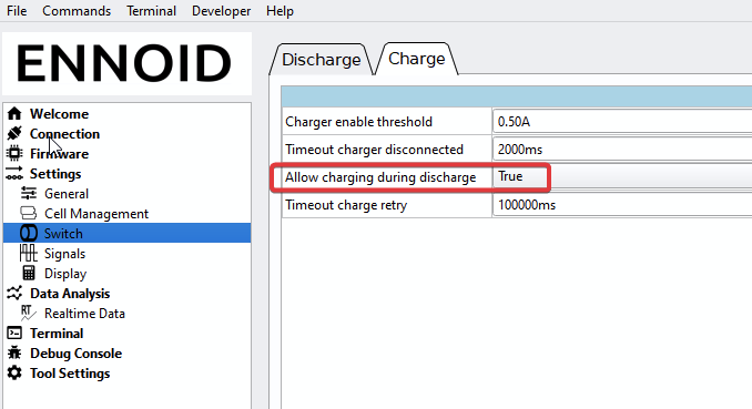
For reference, the charging port does appear to stay live once the voltage is brought up if ‘Allow charging during discharge’ is true. This remains to be the case when the charger is removed from power until the next shut-down.
1 Like
I will repeat again: Use VESC tool for configuring XLITE and do not use ENNOID-BMS tool unless you really know what you are doing.
VESC tool is a lot easier to use and you will not experience unexpected behaviour when using it for configuring.
1 Like
Thanks, that is what I need.
I tested it works.
I.e. we could use Charge port as Load port.
It is great!
@ENNOID
btw I discoverd some bug in CAN telemetry transmittion in version 6.0
It sends a lod of messages 2B(CAN_PACKET_BMS_TEMPS), assuming there are 172 cells.

It does not works in V6.0 jnly in 5.5
i mean
Allow charging during discharge
Could you be a bit more specific about the bug you encountered? Using VESC tool or EBMS tool for configuring? Parameters etc.
There is no such bug in VESC tool over CAN bus and this section uses this particular message… so I doubt there is a bug there unless you do something wrong. Like using your own firmware.
FW: XLITE-12 V2
I observe direct CAN traffic via ESP32RET can sniffer and SavvyCAN SW.
I simply don’t observe this CAN bus issue you are reporting on V6.00 firmware which is available on the website. I tried many different scenarios, using ENNOID-BMS tool and VESC tool for config. Everything seems normal, I receive only one 0x00002b0a. The only CAN message that repeats itself 8 time is related to the 8 x 0x0000290a which correspond to the 8 x 3 = 24 cells voltages.

That is why I’m asking, what is you configuration? Which firmware are you using exactly (from the website or the one included in ENNOID-BMS-tool)? What are your settings? Maybe you have somehow broken the settings when using ENNOID-BMS-tool because it is possible reach 172 temperature channels if you configure with several "monitoring IC count " or many “parallel module count” and also “number of temp sensor per monitoring IC” Maybe you are using an XML file for configuring? Beware, they are a good way to preserve your settings, but are not always compatible between versions. I must update the claim on the ENNOID-BMS-tool settings page, it is confusing
Ok so I’ve got the xlite v2 12p version and I want to use the output/charging for peripherals and lights via a dc buck xfmr.
Would it be possible to add a switch (momentary or latching?) to turn the bms output on? It would be a small load (4.5a +inefficiencies) and just be things that could have a parasitic or unattended load like usb charging circuit so i want to make sure it is downstream from the bms because they wouldn’t have any protective low voltage cutoff.
Assuming this can be done should i fuse the load against a short circuit? Id hate to have a rock hit my led power cable and damage the bms
@ENNOID thoughts? Is this functionally configurable from vesc tool or in the ennoid app? Im gun shy about messing with the settings beyond my previous experience, im good at breaking stuff lol
@ENNOID XLITE-v3 - I noticed high temperature temp hum while charging. 100°C seem excessive and a bit suspicious (19S battery, 5A charger).
I have 2 termistors on cells and they correctly show temperature close to ambient (21°C).
After powering on BMS temp hum rises quickly and settles around 37-40°C on idle, but after starting charge session it raises quickly.
Is this normal behaviour? What are the expected, safe values for temp hum?

I noticed new test firmware -6.1 beta2 and release notes saying that it’s fixing charge thermal protection, so decided to upgrade. It doesn’t seem to change anything.
I set up charge max temp BMS to 60°C, but it doesn’t stop charging after temp hum is 60°C or over