Cyclic loading. Relatively low reversing loads repeated over and over. There are a lot of things that contribute to it but that is usually the failure mode. This is why structural limits can’t be neatly stated by the weight of the rider. Not accurately anyway. The stiffness of the board, the environment it is ridden in, and the weight and style of the rider all contribute to the magnitude of the cyclic loads and the number of cycles the board sees. The local effect of the cyclic loads, the material the component is made of, and the way it is processed determine what cyclic loading will cause a failure. I will try not to make this too long but I will try to address each of those factors. It won’t be a step-by-step of how to perform the dynamic and stress analyses on your board but it will provide a framework to follow if you choose to subject yourself to such torture.
I’m not sure where to start so I will start with the equation of harmonic motion, which includes many of the variables listed above. On a vehicle, such as a skateboard, there are many different vibration inputs in the environment. It is not quite white noise (equal input at all frequencies) but we can rest assured that there will be inputs that will excite almost any vibration mode the vehicle possesses. We are interested in the form that equates to acceleration, since we can directly turn acceleration into force (load).
a = -((omega)^2) * A * (sin((omega) * t)
Where a is acceleration, omega is angular velocity, A is amplitude, and t is time. Omega is stated in radians per second and is determined by the stiffness of the spring and the mass of what is oscillating. For the simple case of a rider carving on a skateboard the stiffness is the stiffness of the board (k) – how far does it deflect when a mass is put on it and the mass (m) of the rider plus whatever portion of the board is in motion when flexing the deck and trucks to carve. The frequency is how often the rider makes a complete right and complete left turn and returns to the initial spot – one cycle. I threw that in here because we will soon need it. The equation for omega is:
omega = (k / m)^0.5
The square root of k over m. I never said there wouldn’t be any math but you too can be an engineer without remembering equations that make your eyes bleed. Do what I do. Use online calculators. If at all possible use SI units because the absurdity of English units becomes readily apparent when you have to deal with pounds force and pounds mass.
Didn’t I define omega two different ways? Good question. Yes I did. There is the “natural frequency” omega defined by the stiffness of the board and the mass of the rider and there is the “actual frequency” the system is operating at. The equation of harmonic motion is for steady state motion. There is no more input and no losses (frictionless). The system will eventually settle to oscillate at it’s natural frequency in such an environment. The rider, however, provides a different input, at his comfortable carving pace. There are additional terms to evaluate motion due to an input in the real world. The amplification, q, and the damping* ratio, zeta. The math gets really messy here and isn’t all that important due to our assumption that the environment provides inputs at all frequencies. What is important to skaters is what these mean to our rides.
The damping ratio is a measure of how friction causes loss in the system. Adding plies to a deck of other materials like fiberglass will increase the damping due to the stiffness variation in the laminate. The amplification is determined by the ratio of the input frequency and the natural frequency. If they match perfectly you get very high amplification. This is that sweet spot you find when your board rebounds you perfectly into the next turn while carving. It is why it is possible to pump a board. You want a lot of amplification for a carving board and a lot of damping for a downhill board. Speed wobbles are the devastating result of too much amplification and not enough damping. Board builders know all this engineering whether they know the theory or not. Engineering is practical application and that is how they make our boards work.
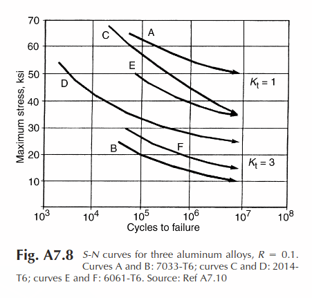
There are many other inputs to our boards when we ride them. We all know the result of riding on a road with a rough surface and know that it happens at a different frequency than our carving inputs. You could use the methods above to calculate the S and n used in the carpet plots that define fatigue failure. It turns out that, like most things mechanical, fatigue is governed by superposition. If you calculate the loss of fatigue life for a number of different frequencies, the individual contributions can be summed to determine the total loss of fatigue life. That would be remarkably tedious but that is what we do in an engineering company. Fortunately, the designs of our components are close enough that we probably don’t need to subject ourselves to the boredom. However, if you have a product you have marketed that is seeing too many failures this is the way to find out why. If you don’t have an engineer available I would recommend hiring a contract engineer stress analyst. It shouldn’t take them more than a few days to work it out.
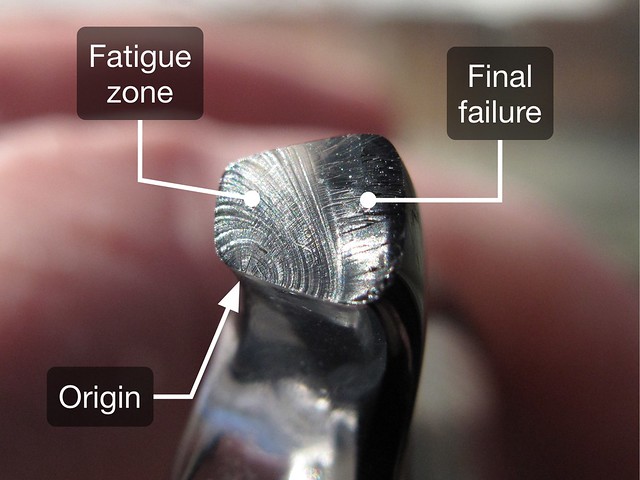
We will get to the S-n curves soon. First a word on what fatigue is. Fatigue is the failure of a part under cyclic loading due to crack growth. We look over our prized components from top to bottom – there aren’t any cracks to grow. Yes there are. There are imperfections in the material, inclusions, that are essentially cracks and behave the same. Cast metallics have many inclusions because they are poured. Plate and bars have fewer because they are rolled. Forgings have the least because they are pressed under great pressure. This is why cast parts of the same thickness will fail sooner than parts machined from bar or a forging, even when they are the same alloy.
S-n curves are carpet plots that show a material’s resistance to fatigue. S is the local stress and n is the number of cycles – the natural frequency for the given mode multiplied by the time it experiences that mode. The S-n curve tells what number of cycles will fail the material at the given stress. The stress is determined by the applied load and the local geometry of the component. A given load, P, applied to a thin section results in a larger stress than the same load P applied to a thicker section. The stress is also dependent on the shape of the cross section (round, rectangular, octagonal, etc.) and the way the load is applied (tension, compression, shear, bending, torsion).
I will end this first installation here. To come: more about S-n curves and shock loads. If there is a topic(s) people want me to expand on I will also do that.
*The proper term is damping, not dampening. Dampening is making the board wet.


 . I love to read and learn, i’ve been involved with esk8 for about 3.5 yrs and i love being around everyone in this forum. I don’t post as much cause i always look for knowledge that has been shared. Thank you for sharing this. Bring on all the lessons to be learned.