Alright Brian, thanks for the info 
I am planning to open up the board to diagnose it before I get back onto riding again, is there any telltale sign of a shorted motor phases?
I wanna ensure it’s fine before getting it back on the road 
Alright Brian, thanks for the info
I am planning to open up the board to diagnose it before I get back onto riding again, is there any telltale sign of a shorted motor phases?
I wanna ensure it’s fine before getting it back on the road
or for the ESC FETs use a multimeter to check
Phase A to Bat +
Phase B to Bat +
Phase C to Bat +
Phase A to Bat -
Phase B to Bat -
Phase C to Bat -
None of those should read under 50 ohms while ESC powered off.
What should I cutoff my battery at, I ran my 10s4p to 36v and want to keep my 30q’s healthy. I see people doing 29v
Depends on what you want.
(all examples for 10S li-ion, for 12S multiply all numbers by 12 and then divide by 10)
If you want full power until it’s dead, try
cutoff start 34V
cutoff end 32V
If you want a slow reduction of power, allowing you to notice it’s dying and have time to limp home, try
cutoff start 35.5V or even 36V
cutoff end 31V
![]() this is what I use
this is what I use
Or to maximize range, try
cutoff start 33V
cutoff end 30V
I’m using what your using already! Lol, I might of asked this question twice to you
So these steps can be done with just the motor alone and no need to connect them to the VESC right?
To be it simple, is connecting referring to just touching the phase wires together?
My apologies if I sound like a total noob because I’m still new to the technical side of things in esk8 
Yes you understood correctly no vesc connected just motor by itself.
Yes, touching them together. If you have two alligator clip test leads it helps a lot, or just hold them touching with your fingers.
Thanks for the guidance bros 
I shall check mine out tonight been riding my scooter to commute instead of the board but safety first
Ah thanks for your answer. That will help me in my search for a new VESC
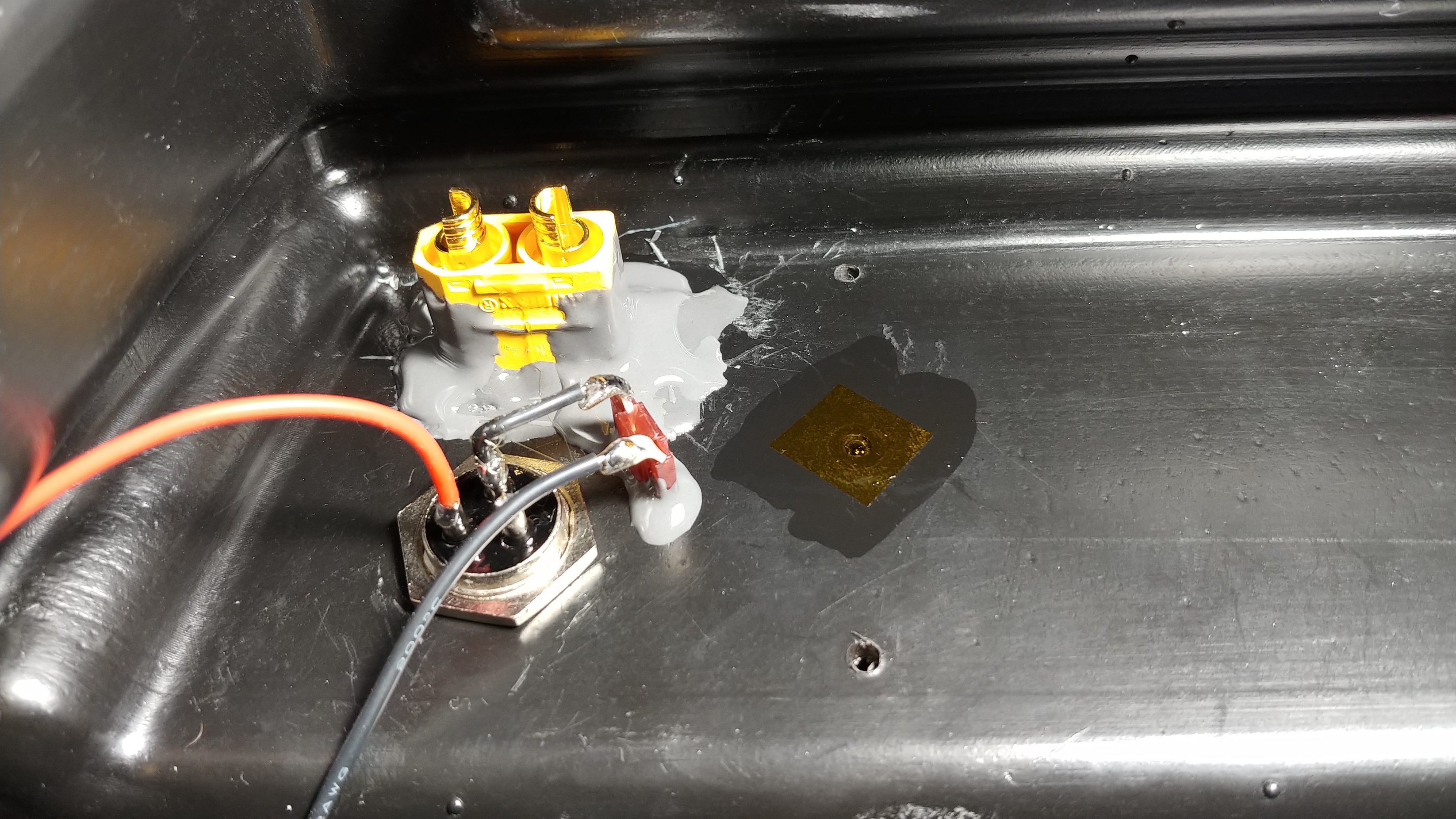
@b264 Does this look okay? I put to much solder on the side pin (black) and it went down the pin and soldered the pin better to the port itself which is a good thing but will the contact be an issue or does this look fine?
I think it looks fine. Don’t forget the fuse.
What bms is it?
Yes, I would solder a fuse inline with either the black or red wire
https://www.mouser.com/ProductDetail/576-099707.5WXN
It’s saved me at least twice
A 7.5A fuse is fine for up to 4A charging
can you post a link or explaine how i do that?
I would potentially insolate the positive wire all the way to the base of the port. That nut could potentially vibrate loose over time and land on top of the solder joints of the + and - terminal and create a short.
I usually put threadlocker on there to prevent that — and then cover the exposed electrical connections with MG Chemicals #419D Acrylic conformal coating in the 55ml bottle with brush-cap (not separate brushes on the side)
yes of course.